lower control arm angle and relocation brackets (an explanation with pictures)
 04-16-2004, 02:04 PM
#1
Supreme Member

Thread Starter

Join Date: Jun 2001
Location: Charleston, SC
Posts: 9,550
Likes: 0
Received 2 Likes
on
2 Posts
Car: 91 Camaro Vert
Engine: 02 LS1, HX40
Transmission: 2002 LS1 M6
lower control arm angle and relocation brackets (an explanation with pictures)
i put this in as a animated gif incase you wanted to share it elsewhere. i hope this helps someone 
if someone has the tools and is willing to draw the frames to make the LCA movement animated, i'll make a second one.

if someone has the tools and is willing to draw the frames to make the LCA movement animated, i'll make a second one.
Last edited by MrDude_1; 05-01-2006 at 01:52 PM.
 04-16-2004, 03:03 PM
#2
Moderator
Join Date: Jan 2000
Location: Mercedes Norte, Heredia, Costa Rica
Posts: 20,981
Likes: 0
Received 9 Likes
on
8 Posts
Car: 1984 Z28 Hardtop
Engine: 383 Carb
Transmission: 4L60
Axle/Gears: 3.54 Dana 44
Let me play with that tonight and I'll render something up showing the whole thing. Might as well show the effect of body roll on it too.
04-16-2004, 03:11 PM
#3
Supreme Member
Thread Starter
Join Date: Jun 2001
Location: Charleston, SC
Posts: 9,550
Likes: 0
Received 2 Likes
on
2 Posts
Car: 91 Camaro Vert
Engine: 02 LS1, HX40
Transmission: 2002 LS1 M6
Originally posted by Apeiron
Let me play with that tonight and I'll render something up showing the whole thing. Might as well show the effect of body roll on it too.
Let me play with that tonight and I'll render something up showing the whole thing. Might as well show the effect of body roll on it too.
here: http://josh.swoca.net/board/mrdude/Lcaangle.zip
when im talking to someone in person, i usually just use a straw between my hands, but ive kinda found it hard to SHOW people online what im talking about....
04-16-2004, 05:10 PM
#4
Supreme Member

Join Date: Apr 2003
Posts: 3,563
Likes: 0
Received 1 Like
on
1 Post
Car: 1991 RS Camaro (Jet Black)
Engine: 95 383 CI (6.3) LT1
Transmission: 95 T-56
Thanks for the lesson mr. dude, now I can see this is gonna be a pretty good upgrade. This is definatley gonna be the next mod I do, i'll do SFC's at the same time, just ordered a spohn t-56 tourque arm, so when I had to the track, it should be interesting.
04-16-2004, 05:30 PM
#5
Moderator
Join Date: Jan 2000
Location: Mercedes Norte, Heredia, Costa Rica
Posts: 20,981
Likes: 0
Received 9 Likes
on
8 Posts
Car: 1984 Z28 Hardtop
Engine: 383 Carb
Transmission: 4L60
Axle/Gears: 3.54 Dana 44
Originally posted by MrDude_1
want the images i used without all the GIF rendering?
want the images i used without all the GIF rendering?
04-17-2004, 11:48 AM
#6
Supreme Member
Thread Starter
Join Date: Jun 2001
Location: Charleston, SC
Posts: 9,550
Likes: 0
Received 2 Likes
on
2 Posts
Car: 91 Camaro Vert
Engine: 02 LS1, HX40
Transmission: 2002 LS1 M6
Originally posted by Apeiron
Nah, I'll throw a 3d model together.
Nah, I'll throw a 3d model together.
04-17-2004, 12:44 PM
#7
Supreme Member

Join Date: Jul 2003
Location: Lima, OH
Posts: 1,096
Likes: 0
Received 0 Likes
on
0 Posts
Car: '89 Formula 350 & '86 Z28
Engine: L98 & 355ci
Transmission: 700r4 in both
Also a good mod for any of our cars, lowered or not. Because it changes the instant center and like you said lifts the rear end because of the pinion climbing the ring gear. Effectively slamming the tire to the ground for intital traction untill the effects of weight transfer come into play 
Trending Topics
04-17-2004, 08:51 PM
#8
Moderator
Join Date: Jan 2000
Location: Mercedes Norte, Heredia, Costa Rica
Posts: 20,981
Likes: 0
Received 9 Likes
on
8 Posts
Car: 1984 Z28 Hardtop
Engine: 383 Carb
Transmission: 4L60
Axle/Gears: 3.54 Dana 44
Originally posted by MrDude_1
just make the end result small enough that i can show people that only have dialup.
just make the end result small enough that i can show people that only have dialup.
 Almost done, just have to animate.
  04-17-2004, 10:29 PM
#10
Supreme Member
Thread Starter
Join Date: Jun 2001
Location: Charleston, SC
Posts: 9,550
Likes: 0
Received 2 Likes
on
2 Posts
Car: 91 Camaro Vert
Engine: 02 LS1, HX40
Transmission: 2002 LS1 M6
Originally posted by CaysE
I wonder where you got those images from, MrDude.
I wonder where you got those images from, MrDude.
06-09-2004, 12:55 AM
#11
Moderator
iTrader: (2)
Join Date: May 2001
Location: Sac, CA
Posts: 5,246
Likes: 0
Received 11 Likes
on
8 Posts
Car: '89 GTA
Axle/Gears: 3.27/9-bolt
had a quick question to add to this thread.
i'm planning on putting the weld style reloc. brackets soon and was curious if it could harm more than hurt regarding the pinion angle being in an incorrect position after they are welded since i wasn't planning on replacing the torque arm.
hope that made sense it's late.
i'm planning on putting the weld style reloc. brackets soon and was curious if it could harm more than hurt regarding the pinion angle being in an incorrect position after they are welded since i wasn't planning on replacing the torque arm.
hope that made sense it's late.
06-09-2004, 01:03 AM
#12
Banned

Join Date: May 2004
Location: Orange, Calif
Posts: 1,340
Likes: 0
Received 0 Likes
on
0 Posts
Car: '87 Cam RS V6
Engine: Top Secret
Transmission: DYT700R4 custom inerts and conv.
Originally posted by OUTATIME GTA
had a quick question to add to this thread.
i'm planning on putting the weld style reloc. brackets soon and was curious if it could harm more than hurt regarding the pinion angle being in an incorrect position after they are welded since i wasn't planning on replacing the torque arm.
hope that made sense it's late.
06-09-2004, 02:07 AM
#14
Supreme Member
iTrader: (5)
Join Date: Apr 2002
Location: Roscoe, IL
Posts: 1,704
Likes: 0
Received 1 Like
on
1 Post
Car: 1991 Trans Am
Engine: LQ4
Transmission: T-56
Axle/Gears: 3.70
the brackets dont just have the holes straight down, that would mess up the pinion angle. they holes are the same length away from the mount on the body to the stock mount on the rear end. heres a pic from spohns website. notice the new mounting holes are closer then the stock one on the top
The following users liked this post:
Morphues (10-23-2022)
06-09-2004, 02:50 AM
#15
Senior Member

Join Date: Nov 2003
Location: Gary, In USA
Posts: 586
Likes: 0
Received 1 Like
on
1 Post
Car: '85 Camaro
Engine: LG4 305
Transmission: T-5
So you need to do LCAs when you've lowered the car? They are mounted along the arc the pinion would normally travel? Are they the opposite of ladder bars, or do they work in conjunction with them?
The following users liked this post:
philrthompson (07-20-2021)
06-09-2004, 03:55 AM
#16
TGO Supporter
Join Date: Jul 1999
Location: Another world, some other time
Posts: 3,838
Likes: 0
Received 4 Likes
on
4 Posts
Car: 86 LG4 & 92 TBI Firebird
Engine: The Mighty 305!
Transmission: 700R4
Axle/Gears: 3.42
LCA brackets have nothing to do with the pinion angle. The reason the holes are drilled in an arc is to keep the rear centered (fore/aft) in the wheel wells. If they weren't arced, you'd have to adjust the length of the LCA.
06-09-2004, 05:24 AM
#17
Supreme Member
Join Date: Jul 2003
Location: Lima, OH
Posts: 1,096
Likes: 0
Received 0 Likes
on
0 Posts
Car: '89 Formula 350 & '86 Z28
Engine: L98 & 355ci
Transmission: 700r4 in both
Originally posted by Justins86bird
LCA brackets have nothing to do with the pinion angle. If they weren't arced, you'd have to adjust the length of the LCA.
LCA brackets have nothing to do with the pinion angle. If they weren't arced, you'd have to adjust the length of the LCA.
 06-13-2004, 12:32 AM
#19
Senior Member

Join Date: Apr 2003
Location: Rochester, NY
Posts: 667
Likes: 0
Received 0 Likes
on
0 Posts
I was just trying to figure out why people talk about mods to control arms when lowering their cars. Thanks great explanation:hail:
This will definitely help with accelaration. Does LCA angle have any effects on cornering?
This will definitely help with accelaration. Does LCA angle have any effects on cornering?
06-13-2004, 04:51 PM
#20
Senior Member
Join Date: Jul 1999
Location: N.J. USA
Posts: 506
Likes: 0
Received 1 Like
on
1 Post
Car: Formula
Engine: 305 TPI
Transmission: M5
Is it necessary to use the LCA relocation brackets if you're only going to lower the car an inch? I'm planning on getting KYB's and an Eibach Pro-Kit. I already have Lakewood arms .
06-13-2004, 05:35 PM
#21
Supreme Member
Join Date: Jul 2003
Location: Lima, OH
Posts: 1,096
Likes: 0
Received 0 Likes
on
0 Posts
Car: '89 Formula 350 & '86 Z28
Engine: L98 & 355ci
Transmission: 700r4 in both
Yes if you want any traction.....
Unless you are someone who thinks it cool to burn your tires all the time")
Unless you are someone who thinks it cool to burn your tires all the time
06-13-2004, 08:53 PM
#22
Member
Join Date: Nov 2000
Location: Ormond Beach, Florida
Posts: 212
Likes: 0
Received 0 Likes
on
0 Posts
Car: '88 Firebird Formula
Engine: 360hp/417ft. lb. 350
Transmission: Pro-Built Street/Strip 700R4
Originally posted by TPIterror
Is it necessary to use the LCA relocation brackets if you're only going to lower the car an inch? I'm planning on getting KYB's and an Eibach Pro-Kit. I already have Lakewood arms .
Is it necessary to use the LCA relocation brackets if you're only going to lower the car an inch? I'm planning on getting KYB's and an Eibach Pro-Kit. I already have Lakewood arms .
Help?
 06-13-2004, 09:29 PM
#23
Senior Member
Join Date: Jul 1999
Location: N.J. USA
Posts: 506
Likes: 0
Received 1 Like
on
1 Post
Car: Formula
Engine: 305 TPI
Transmission: M5
Originally posted by SweetS10v8
Yes if you want any traction.....
Unless you are someone who thinks it cool to burn your tires all the time
Yes if you want any traction.....
Unless you are someone who thinks it cool to burn your tires all the time
Well, no of course...duh.
I used to hop like a madman until I got the Lakewood arms. I'm used to hooking up nice now, so I'd like to keep it that way. An inch lower doesn't sound too drastic though, so I'll make my decision whether or not to get the brackets based on how I hook up after the new springs.
06-14-2004, 08:06 AM
#24
Supreme Member
Thread Starter
Join Date: Jun 2001
Location: Charleston, SC
Posts: 9,550
Likes: 0
Received 2 Likes
on
2 Posts
Car: 91 Camaro Vert
Engine: 02 LS1, HX40
Transmission: 2002 LS1 M6
just stick your new springs on.. if its off, its off, if its not, its not.
just keep in mind that if its close, when the weight transfers back, if it squats, it'll move past horizontal and then start to break loose.
lots of stock sagging springed cars have this problem, and some MILDLY lowered ones dont.... mainly because saggy springs can lower the car over 2" while lowering springs are rated from stock full height.... but in anycase, you wont know till you try, and what worked on your car, might not work for someone elses.
worse case, its off, and your launches suck until you spend $80 on relocation brackets.


 06-24-2004, 07:08 AM
#27
Supreme Member
Join Date: Jul 2003
Location: Lima, OH
Posts: 1,096
Likes: 0
Received 0 Likes
on
0 Posts
Car: '89 Formula 350 & '86 Z28
Engine: L98 & 355ci
Transmission: 700r4 in both
Heres the best way I can explain it, just quoted myself from another post from another post
Originally posted by SweetS10v8
The big difference will come with LCA relocation brackets(LCARBS). From the factory your LCAs are almost parallel to the ground, which puts your Instant center towards the front of the car.
It has to do with your instant center, or imaginary lift point on your car. When you launch the LCARBs help you because they move the instant center(IC) towards the back of the car.
The farther back the IC is the harder the tire will hit on inital launch(before the affects of weight transfer come into play). This is from pitch rotation(resistance to wheels turning, pinion climbing the ring gear) So, before the tires move, the pinion tries to climb the ring gear, lifting the rear of the car and actually slamming the tires into the ground for intial traction.
After that happens weight transfer takes over and keeps the tires planted from the weight of the car as it accelerates. Like I said in the begining the farther back the IC is the harder the tire "hit" initally, but also the less affect you get from weight transfer. So conversley the Farther out the IC is the less slamming affect occurs and more weight transfer happens!
Last edited by SweetS10v8; 06-24-2004 at 10:52 AM.
06-24-2004, 07:22 AM
#28
Supreme Member
Join Date: Mar 2001
Location: Portland, OR www.cascadecrew.org
Posts: 6,577
Likes: 0
Received 0 Likes
on
0 Posts
Car: 1990 Camaro RS
Engine: Juiced 5.0 TBI - 300rwhp
Transmission: T5
Axle/Gears: 3.42 Eaton Posi, 10 Bolt
Close but no cigar.
The IC is the point in which the LCA's plane crosses the SVSA lenght of the torque arm (mount)
the angle of the torque arm really doesn't effect the anti-squat properties. but the location of the mount DOES. that is why there are shorter torque arms. if it was all do to the angle of the TA, then lenght wouldn't be such a factor.
I didn't read the entire thread, so it may have come up. but remeber under braking, the iC location can come back to haunt you, if you go too far up/back, you can cause wheel hop under heavy braking.
06-24-2004, 07:28 AM
#29
Supreme Member
Join Date: Jul 2003
Location: Lima, OH
Posts: 1,096
Likes: 0
Received 0 Likes
on
0 Posts
Car: '89 Formula 350 & '86 Z28
Engine: L98 & 355ci
Transmission: 700r4 in both
Whats SVSA?
I wasnt talking anything about TQ arm, just how relocation brackets for the LCAs change things, assuming a stock TQ Arm. I could be way off, but thats how It was explained to me.
And yes you can go too far back and up with the IC, i just suspect that the relocation brackets wont allow for that much adjustment.
Last edited by SweetS10v8; 06-24-2004 at 07:32 AM.
06-24-2004, 07:32 AM
#30
Supreme Member
Join Date: Mar 2001
Location: Portland, OR www.cascadecrew.org
Posts: 6,577
Likes: 0
Received 0 Likes
on
0 Posts
Car: 1990 Camaro RS
Engine: Juiced 5.0 TBI - 300rwhp
Transmission: T5
Axle/Gears: 3.42 Eaton Posi, 10 Bolt
you are close. but it not where the points cross.
what happens if you have a negative angle? the points don't cross.
the SVSA is Side View Swing Arm. it is refering to the lenght of the torque arm. the IC is the location of where the line extended from the LCA's crosses the plane created at the length of torque arm.
what happens if you have a negative angle? the points don't cross.
the SVSA is Side View Swing Arm. it is refering to the lenght of the torque arm. the IC is the location of where the line extended from the LCA's crosses the plane created at the length of torque arm.
06-24-2004, 07:42 AM
#31
Supreme Member
Join Date: Jul 2003
Location: Lima, OH
Posts: 1,096
Likes: 0
Received 0 Likes
on
0 Posts
Car: '89 Formula 350 & '86 Z28
Engine: L98 & 355ci
Transmission: 700r4 in both
Ok I see where Im off then, On a 4 link how the top bar determines the length of the IC, whereas here its detemined where the mount is. more like a ladder bar with and adjustable bottom link.
The instant center of the lowered car is actually behind it. The lines would only cross behind the vehicle
Im thinking more of the line of a true 4 link, my bad. Like you said, close, but no cigar.
The instant center of the lowered car is actually behind it. The lines would only cross behind the vehicle
Im thinking more of the line of a true 4 link, my bad. Like you said, close, but no cigar.
 06-28-2004, 08:51 PM
#34
Supreme Member
Join Date: Jul 2003
Location: Lima, OH
Posts: 1,096
Likes: 0
Received 0 Likes
on
0 Posts
Car: '89 Formula 350 & '86 Z28
Engine: L98 & 355ci
Transmission: 700r4 in both
I had to do some more research.....
Here is what I found. Got it from here
Shows it is the imaginary intersection of LCAs and TQ Arm???
Not trying to discredit, just trying to fully understand
Here is what I found. Got it from here
Shows it is the imaginary intersection of LCAs and TQ Arm???
Not trying to discredit, just trying to fully understand
04-13-2005, 08:39 AM
#35
Senior Member
iTrader: (1)

Join Date: Jan 2002
Location: MI
Posts: 575
Likes: 0
Received 0 Likes
on
0 Posts
Car: I
Engine: Taunt
Transmission: Mustangs
Back from the dead...
I feel this thread needs a little bit of closure because the last two diagrams directly contradict each other. I'll take a stab at explaining which one is right and why with the hopes that one of the more knowledgeable members on here will either confirm my statement or correct me if I am wrong. Here goes nothing:
The instant center shown on the last image (the one from carcraft.com) does not take into account the fact that the torque arm to rear end connection is designed to resist the torque (moment) the rear end produces while accelerating the car. How they have it drawn, this torque would be resisted by a combination of efforts from the upper and lower links just like how a 3 or 4 link rear suspension would (which a torque arm suspension is neither). The image up a little more (posted by Dewey) does show the torque arm resisting these forces as I believe it should and shows the instant center where I think it should be.
Can I get an Amen??
05-01-2006, 01:53 PM
#36
Supreme Member
Thread Starter
Join Date: Jun 2001
Location: Charleston, SC
Posts: 9,550
Likes: 0
Received 2 Likes
on
2 Posts
Car: 91 Camaro Vert
Engine: 02 LS1, HX40
Transmission: 2002 LS1 M6
ttt..
i was just looking for this thread to show someone the pic, and the pic was down....
its probly been down for years.. heh
fixed and back up.
i was just looking for this thread to show someone the pic, and the pic was down....
its probly been down for years.. heh
fixed and back up.
05-04-2006, 01:41 PM
#37
Supreme Member
iTrader: (1)
Join Date: Jul 2004
Location: Calgary, AB, Canada
Posts: 10,763
Likes: 0
Received 4 Likes
on
4 Posts
Car: 1982 Trans-Am
Engine: 355 w/ ported 416s
Transmission: T10, hurst shifter
Axle/Gears: 10 bolt, true-trac, 3.73
Can I get an Amen??
 05-05-2006, 12:13 PM
#38
Supreme Member

Join Date: Apr 2002
Location: Southwest Florida
Posts: 4,627
Likes: 0
Received 1 Like
on
1 Post
Car: projects.......
good info, shows what that little search key can do for ya
..although this is an old post:
- Ladder bar's lift the car, thus pushing the rear tires to the ground for traction. They also are mounted solid at the front, thus allowing them to transfer the forward momentum of the diff/tires to the car.
- LCA's simply push forward on the car/up, they don't control the downward force on the diff, thats what the tq arm is for. The greater the angle of the control arm, the more it helps traction/lift, but the straighter you can run them while still maintaining traction will move the car forward faster, instead of trying to push up.
Remember, up is wasted momentum. You want to go forward.
..although this is an old post:
Are they the opposite of ladder bars, or do they work in conjunction with them?
- LCA's simply push forward on the car/up, they don't control the downward force on the diff, thats what the tq arm is for. The greater the angle of the control arm, the more it helps traction/lift, but the straighter you can run them while still maintaining traction will move the car forward faster, instead of trying to push up.
Remember, up is wasted momentum. You want to go forward.
05-19-2006, 11:59 AM
#40
Supreme Member
Join Date: Apr 2002
Location: Southwest Florida
Posts: 4,627
Likes: 0
Received 1 Like
on
1 Post
Car: projects.......
here is a question. if i lower my car and have ladder bars i dont have to use lca's??????????
05-19-2006, 03:34 PM
#41
Supreme Member
Join Date: Mar 2001
Location: Portland, OR www.cascadecrew.org
Posts: 6,577
Likes: 0
Received 0 Likes
on
0 Posts
Car: 1990 Camaro RS
Engine: Juiced 5.0 TBI - 300rwhp
Transmission: T5
Axle/Gears: 3.42 Eaton Posi, 10 Bolt
Originally Posted by SweetS10v8
The instant center of the lowered car is actually behind it. The lines would only cross behind the vehicle
This is not correct. The IC will still be in front of the rear axle. But, it will be located below ground level. The IC is the point at which the LCA plane, crosses the TA mount plane.
and Dustin Mustang. AMEN.
The diagram I posted, is taken directly from the Milleken book (aka, the Bible).
05-20-2006, 12:46 AM
#42
Member
iTrader: (4)

Join Date: Apr 2004
Location: New Orleans
Posts: 318
Likes: 0
Received 0 Likes
on
0 Posts
Car: CAMARO
Engine: 383 LT1
Transmission: T 56
Axle/Gears: 3.73
nah. i dont have lca, i am about to replace my rear with a dana 44 and ladder bars, so do i need to lower the car first before i hook up the ladder bars, or is it okay to install them and then lower my car.. thanks
05-21-2006, 12:36 AM
#43
Junior Member

Join Date: Aug 2003
Location: Lehigh Valley area of PA
Posts: 38
Likes: 0
Received 0 Likes
on
0 Posts
Car: $150 82 Camaro
Engine: 406 when my ship comes in
Transmission: 6 speed Richmond (its that ship business again)
The Car Craft article does a good job of explaining IC's. The third gen torque arm replaces the upper links in a 4 link. The rear lower control arms replace the lower links in a 4 link. The following applies;
(1) The IC of the TA is a line drawn through the front mounting point and the center line od thr rear axles and extended beyond both ends of the car. (The pinion angle has no effect on this line)
{2} The IC of the RLCA is a line drawn through the front and rear RLCA mounting points and extended beyond both ends of the car.
(3) One of three things occurs
(A) The two lines intersect behind the car's rear axle because the RLCA's front mounting point is lower then the rear RLCA mounting point. This is common on stock and lowered cars. It causes negative antisquat (the rear of the car squats on hard acceleration and looses traction as a result of poor weight transfer)
(B) The two lines are parallel and zero antisquat occurs. This results in no meaningful weight transfer which does not help acceleration.
(C) The two lines meet in front of the the car's rear axle. This results in positive antisquat (the rear of the car lifts and so does the front of the car). This results in the most weight transfer and the best traction. The most lift occurs when the IC is at the center of the driveshaft's front U joint and the TA front mount is also at the center of the front U joint. Then the driveshaft and the TA both apply their leverage at the same point.
(4)The long and short of TA's
(A) Long arms have a slower rate of weight transfer
(B) Short arms have a faster rate of weight transfer
Think of a lever annd fulcrum with the one end of the lever under the rear axle, the fulcrum as the point where the ring and pinion gears meet and the other end lever at the TA's front mounting point. The weight you want to lift is on the front end of the TA and the force is applied at the axle. This is over simplified to show the theory that the ratio between the length of the lever and location of the fulcrum effect the speed the weight is lifted.
(5) In real life there are other veriables that that enter into acceleration and weight transfer, but they do not affect the basic geometry stated above, they only add to or subtract from the results. These veriables are;
(A) Available traction built into the tires. This is based on tire design and the amount of weight that can be affectively placed on them.
(B) The amount of torque available (self explanitory)
(C) The rear spring rates,if antisquat is built into the rear suspension and the car still squats stiffer springs are needed.
(D) Shock rates that match the spring rates will control wheel hop and the rate of front to rear weight transfer.
(E) Rear roll rate (side to side weight transfer), too much or too little weight is transfered to one rear wheel effecting traction.
(F) If the IC, as described above, does not fall on the front mounting point of the TA, it will either aid or hinder the effectiveness of weight transfer by changing the effective lenght of the TA.
I hope this helps to clarify this issue. Now about those ladder bars. If they have two rear mounting points, one above and one below the rear axle and one front mounting point, they should be mounted as far towards the outboard ends of the rear housing as possible, parallel to the driveshaft and the front mount becomes the IC. The TA and the RLCA's should be eliminated, but the panhard bar or some other type of side to side locating system must be used. A front mounting point above the upper rear mounting point increases front to rear weight transfer. A front mounting point below the upper rear mounting point reduces weight transfer. Lowering the car lowers the front mounting point if you mount them first.
Last edited by Al Miles; 05-22-2006 at 08:30 PM.
05-22-2006, 12:13 PM
#44
Supreme Member
Join Date: Apr 2002
Location: Southwest Florida
Posts: 4,627
Likes: 0
Received 1 Like
on
1 Post
Car: projects.......
The third gen torque arm replaces the upper links in a 4 link. The rear lower control arms replace the lower links in a 4 link. The following applies;
(1) The IC of the TA is a line drawn through the front mounting point and the center line od thr rear axles and extended beyond both ends of the car. (The pinion angle has no effect on this line)
{2} The IC of the RLCA is a line drawn through the front and rear RLCA mounting points and extended beyond both ends of the car.
(3) One of three things occurs
(A) The two lines intersect behind the car's rear axle because the RLCA's front mounting point is lower then the rear RLCA mounting point. This is common on stock and lowered cars. It causes negative antisquat (the rear of the car squats on hard acceleration and looses traction as a result of poor weight transfer)
(B) The two lines are parallel and zero antisquat occurs. This results in no meaningful weight transfer which does not help acceleration.
(C) The two lines meet in front of the the car's rear axle. This results in positive antisquat (the rear of the car lifts and so does the front of the car). This results in the most weight transfer and the best traction. The most lift occurs when the IC is at the center of the driveshaft's front U joint as the as the TA and driveshaft both apply their leverage in the same plane.
(4)The long and short of TA's
(A) Long arms have a slower rate of weight transfer
(B) Short arms have a faster rate of weight transfer
Think of a lever annd fulcrum with the one end of the lever under the rear axle, the fulcrum as the point where the ring and pinion gears meet and the other end lever at the TA's front mounting point. The weight you want to lift is on the front end of the TA and the force is applied at the axle. This is over simplified to show the theory that the ratio between the length of the lever and location of the fulcrum effect the speed the weight is lifted.
(5) In real life there are other veriables that that enter into acceleration and weight transfer, but they do not affect the basic geometry stated above, they only add to or subtract from the results. These veriables are;
(A) Available traction built into the tires. This is based on tire design and the amount of weight that can be affectively placed on them.
(B) The amount of torque available (self explanitory)
(C) The rear spring rates,if antisquat is built into the rear suspension and the car still squats stiffer springs are needed.
(D) Shock rates that match the spring rates will control wheel hop and the rate of front to rear weight transfer.
(E) Rear roll rate (side to side weight transfer), too much or too little weight is transfered to one rear wheel effecting traction.
(F) If the IC, as described above, does not fall on the front mounting point of the TA, it will either aid or hinder the effectiveness of weight transfer by changing the effective lenght of the TA.
05-22-2006, 02:16 PM
#45
Supreme Member
Join Date: Mar 2001
Location: Portland, OR www.cascadecrew.org
Posts: 6,577
Likes: 0
Received 0 Likes
on
0 Posts
Car: 1990 Camaro RS
Engine: Juiced 5.0 TBI - 300rwhp
Transmission: T5
Axle/Gears: 3.42 Eaton Posi, 10 Bolt
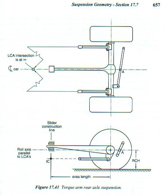
Al, how are you figuring anti-squate. the IC of the rear suspension is NOT behind the axle. The AS is a calculation based on the IC, and a line drawn back from the center of the tires contact patch. I the inclination of the TA has no effect on the IC location, that is based PURELY on lenght. As I posted in the Milliken picture earlier. Here is diagram for figuring AS on a torque arm suspension.
05-22-2006, 08:14 PM
#46
Junior Member
Join Date: Aug 2003
Location: Lehigh Valley area of PA
Posts: 38
Likes: 0
Received 0 Likes
on
0 Posts
Car: $150 82 Camaro
Engine: 406 when my ship comes in
Transmission: 6 speed Richmond (its that ship business again)
lower control arm and relocation brackets (an explanation with pictures)
Please look at SweetS10V8's post of 6-24-2004 as it describes in a picture the way to determine the IC of a 3rd gen rear suspension. If the front mounting point of the RLCA is lower than the rear mounting point, the IC of the rear suspension falls behind the rear axle. At first your attachment had me confused until I realized there are many instant centers used to calculate the specific desired results. The IC you see on your attached drawing is used to calculate the percentage of positive or negative antisquat, it is NOT the IC of the rear suspension. Just as you incorrectly refered to a set of drawings in your post of 6-24-2004 that shows the IC of the rear roll center of the 3rd gen as the IC of the rear suspension. An Instant Center (IC) is a point where two lines in the same plane cross at a given point in time and certain actions taking place in this plane are centered on this point. I am not familiar with the Milliken book, but I have read several others in 46 years of building drag race and stock cars as well as street machines. Right now my $150 Camaro is completely stripped to the bare body, has a 10 pt S&W cage, a completely adjustable (spring heights, arm mounting points and arm lengths) chrome moly tubing rear suspension and I'm working on mini tubs. Please reread your book (a picture and a thousand words are better than one or the other) and the above posts and maybe we can agree on some suspension basics so everyone can benifit.
05-22-2006, 10:33 PM
#47
Supreme Member
Join Date: Mar 2001
Location: Portland, OR www.cascadecrew.org
Posts: 6,577
Likes: 0
Received 0 Likes
on
0 Posts
Car: 1990 Camaro RS
Engine: Juiced 5.0 TBI - 300rwhp
Transmission: T5
Axle/Gears: 3.42 Eaton Posi, 10 Bolt
Originally Posted by Al Miles
Please look at SweetS10V8's post of 6-24-2004 as it describes in a picture the way to determine the IC of a 3rd gen rear suspension. If the front mounting point of the RLCA is lower than the rear mounting point, the IC of the rear suspension falls behind the rear axle.
Think about the forces there, and then think about how a 4-link handles them, how a 3 link handles them, then how a troque arm handles them.
In both the 3 link, and 4-link, the torque of the rear axle, is transmited by compressing the upper link(s), so you instant center is calculated by extending that plane. A torque arm does not work that way.
Please, look again, at the my original post with the picture taken from the Milleken handbook (Being a suspension guru, I am sure you know what that book is). No where in either of my diagrams (neither of which I made), does the plane extend with the torque-arm. It extends in the direction of the force(s). In the case of the torque arm, it is the verticle plane, in the dirction in which the SVSA transmits the force to the T/A mount.
Also notice, in my last picture, the way the LCA's are oriented, the FRONT of the mount is DOWN, the Instant Center, is NOT behind the car.
05-23-2006, 01:11 AM
#48
Junior Member
Join Date: Aug 2003
Location: Lehigh Valley area of PA
Posts: 38
Likes: 0
Received 0 Likes
on
0 Posts
Car: $150 82 Camaro
Engine: 406 when my ship comes in
Transmission: 6 speed Richmond (its that ship business again)
lower control arm angle and relocation brackets (an explanation with pictures)
Please read my last post again
(1) I said I am NOT familiar with that particluar author and I will add that you may rest assured he is NOT the only published expert
(2) Your drawing shows the IC used in a formula (which I am sure is given in the text) to determine the percentage of antisquat. I recall some of the details of this calculation which I read at sometime in the past (my senior mind is sometimes clouded by age). Under acceleration, any percentage below 100% allows for the rear to squat (negative antisquat). At 100% the IC of the rear suspension is infinity (the TA and the RLCA mounting points are parallel and the lines never meet) and at 101% and above body lift (positive antisquat) occurs.
(3) If you are having a problem understanding the concept of Instant Centers I will be glad to try to explain them again or maybe someone else could step in and help.
(A) IC's are a point in space where two or more lines of force meet at a specific time (they are theoritical, based on mathametical formulas)
(B) The Instant ( a moment in time) Center ( the point in physical space) is number to be plugged into a formula (mathametical calculation) to provide a description of what is physically taking place.
(c) There are different IC's to explain different actions taking place at the same moment in time in different parts to the car's suspension.
Our two examples are the rear suspension as viewed from the side and as viewed from the rear.
The side view has a suspension IC which is a point determined by the mounting points of the TA and RLCA's. (please go back with an open mind and you will see that I am stating correct theory) To make better use of this theory another formula was developed which converts information from the first theory into a percentage (note your drawing shows a percentage figure as the final result) which is useful to eveluate the results of changes made to the IC
The rear view you posted earlier is of the IC of body roll when turning. On a panhard bar suspension it is where the panhard bar crosses the center line of the car. It is changed by raising or lowering one end of the bar (usually the mounting point on the body- a track bar adjustment in NASCAR).
I have studied your picture and have concluded;
(1) The text related to this drawing is needed to completely understand the concept presented
(2) My thoughts without reading the text are;
(A) The formula is for the percentage theory described above
(B) The IC on the drawing is the point where the two lines cross. One line (blue) being drawn through the RLCA mounting points and the other (red) being drawn from the center of the rear tire contact patch to some point in the front of the car. I suspect the front roll center.
(C) The verticle line is confusing, I think it is there only to highlight the IC described in above section (B). I think it is coinsidental that the front mounting point of the TA is on the line. This is because any movement in the RLCA mounting points changes the IC. Also by deffinition an IC must be a point, it cannot be a line.
(D) When antisquat above 100% exists, the blue line crosses the red line behind the tire contact patch and below ground level which explains why lift occurs.
(3) There is no real difference in the end results between a 3rd gen and a 4 link. Both transfer the power through the lower link. For every action there is an oppsite and equal reaction. The tires rotate in one direction while the rear housing tries to rotate in the oppsite direction, the torque arm stops this rotation the same as the top link on a four link stops rear end rotation.
I hope this helps us to get on the same page.
Last edited by Al Miles; 05-23-2006 at 01:19 AM.
05-23-2006, 09:20 AM
#49
Supreme Member
Join Date: Mar 2001
Location: Portland, OR www.cascadecrew.org
Posts: 6,577
Likes: 0
Received 0 Likes
on
0 Posts
Car: 1990 Camaro RS
Engine: Juiced 5.0 TBI - 300rwhp
Transmission: T5
Axle/Gears: 3.42 Eaton Posi, 10 Bolt
Al, The torque arm does not work like the upper links on a 4-link. Because of the sliding link. IF the torque arm had mounting points the it pivoted around on both ends, then yes, the calculation would be done by extending the plane of the upper suspesion member, but that type of suspension is called a three link.
Since the torque arm does not pivot, but instead has a sliding link, you need to figure the IC based on the construction line, which is the direction of the force, in our case, it is percendicular to the torque arm.
As for the text that goes along with my picture. I will QUOTE the Milliken's
"Next a line is drawn perpendicular to the front end of the torque beam where it is attached at its rubber slider joint. This is basically a vertical line."
I do not need to re-read what you said, and I did not miss understand what you said. Plain and simple, you are wrong, and the car-craft picture is wrong. I am posting a picture straight from what is considered the most in depth suspension dynamics book, ever writen, and quoting the authors. Maybe instead of rehashing bad tech posted by another member, and car craft's confusion on the 3-link vs. Torque Arm suspensions, you should do the research yourself. Go get the Milliken's book, and look it up for yourself.
Race Car Vehicle Dynamics (R146) -- William & Douglas Milliken
--John
Last edited by Dewey316; 05-23-2006 at 11:07 AM.
05-23-2006, 11:24 AM
#50
Banned

Join Date: May 2006
Posts: 6
Likes: 0
Received 0 Likes
on
0 Posts
Al,
In all due respect to your knowledge on drag cars...
The IC on a torque arm suspension is centered fore and aft on the torque arm length. The parallel imaginary line from the LCA angle crossing that vertical plain of the torque arm "length" is what determines the HEIGHT off the ground of the IC especially when involving drag launch weight transfer under it OR up over it loading the rear tires.
When the LCA's invert to high of an angle upward in the forward direction, then the IC is raised so high that most cars do not have the traction and/or power to lift the nose weight and rotate it up over the tall IC point. Alot of peple here misconstrue the need for RLCA brackets to be adjusted properly and not just to use the lowest setting.
Furthermore, these lower RLCA mount points cause detrimental handling affects on cornering also by inducing roll oversteer and and exaggerating these cars already notorious push/then snap oversteer affect into and out of a corner.
Dean
Last edited by 2tone; 05-23-2006 at 11:34 AM.