When you click on links to various merchants on this site and make a purchase, this can result in this site earning a commission. Affiliate programs and affiliations include, but are not limited to, the eBay Partner Network.
LTX and LSXPutting LT1s, LS1s, and their variants into Third Gens is becoming more popular. This board is for those who are doing and have done the swaps so they can discuss all of their technical aspects including repairs, swap info, and performance upgrades.
Afternoon folks. Many of us have 100% gutted the electrical from the firewall forward (and several folks much further than that!) and these days every thread that mentions electrical have several very smart folks commenting about how to setup power distribution to more modern/robust standards. Information on what to run, how big the wires should be, etc. is spread through quite a few build and Q&A threads. I'm in the boat right now of starting to rewire the power distribution in my own car, reading all the good threads, and hesitating before I buy yet more parts. This gave me an idea.
Experts Needed!
If you feel qualified to post what you've done when rewiring the power distribution/grounds (and why!), or what you believe should be done (solid knowledge without your own car to show is welcome!) - this is your thread. Post your diagrams and advice please.
Have a Question? If you have a question specifically for your car right now, best bet would be to make a separate thread. However, if you have a question you think would be fairly common and ought to be called out and answered - post it. As consensus is reached, I'll move it to the FAQ post below.
Refinement Process
In general, as the post progresses and there is consensus being shown, I'll summarise and expand the first few posts with that information so it's easy for others to find. This will include - establishing FAQ, listing external and thirdgen resources, and iterating on diagrams until they are as clear as possible, etc.
I'll start by reserving a few empty posts for future use, and tagging those I've been reading most often these days.
NEW SYSTEM (MAD Electrical) - plenty of write-up. Comparison between different decades' electrical systems. Page 2 has the diagram for the "New System"
Improved Electrical System (How to build Hotrods) - an implementation/variant of MAD's "New System". Includes diagram and short write-up.
General Motors Upfitter Integration Guides - particularly the Electrical one. Has solid recommendations when extending GM harnesses, wire selection, cable ampacity, and lots more. If you're wanting to read up on how to do auto electrical and have it look (and work) professionally, this is a solid resource.
Vendors
Ron Francis Wiring - Started in 1974, offers electrical products for the street rod and hot rod industry. Their catalog is more than just parts, it has a lot of recommendations, lessons learned, and theory, particularly as you get toward the back.
Waytek - Lots of electrical/wiring products and excellent quality.
C.E. Auto Electric Supply - plenty of electrical/wiring products, geared for automotive. Good source for "power distribution" products, like underhood bussed electical centers (UBEC) (e.g. "fuse boxes"), with a good "configurator" tool for determining if it will fit all you need. Members have also used them for custom battery cables.
Just to kick off some ideas, here is a device I used to centralize power distribution and get rid of the fusible links in my car.
This is a Littlefuse MTR sealed power distribution module, rated at 60 Amp continuous. It has 4 sockets with a mix of ATO and JCASE fuses (slow blow). I run the whole car off this thing except for the fuel pump and Holley EFI main power (10 AWG wires). That’s how I work around the 60A rating. And alternator cable goes directly to battery and does not touch this device.
The module is fed by a 4 AWG cable directly from Battery B+. These are my circuits,
Subsystems 1 and 2: The wires that were originally on Fusible Links A and B (pass thru C100). These are the wires that originally powered 99% of the car. I snipped off the fusible links and gave each wire a fuse slot.
Subsystem 3: HVAC high-speed fan. Snipped off the fusible link and gave the wire a fuse slot.
Subsystem 4: Underhood power center for engine
Again, the fuel pump and Holley ECM get power directly from battery with inline fuses.
The drawback to this thing is the current rating, and the limited number of circuits. I’m out of room and any add-ons to my car have had to be wired to battery with inline fuses.
* MTR fuse block (p/n BPDMA104HXF1)
* Metri Pack 280 series, 10-12 AWG female wire terminals (p/n 12077413). These are for the ATO fuses. You will also need appropriate size wire seals.
* Delphi Ducon 6.3, 10-12 AWG male wire terminals (p/n 15344631). Used with the JCASE fuses.
* Wire seals for use with Ducon connectors (p/n 12052668)
This was the big shocker when I whittled down my harness to the basics.... These are the wires that powered 99% of my car when stock.
The factory does an amazing job of minimization sometimes. Which is NOT, in and of itself, a bad thing. Using only as much as is needed, and no more, holds down weight, size, cost, etc. etc. etc.
The problem for people like us of course is, when we want to add or change or modernize something, there's no "spare" capacity anywhere.
The correct answer is almost NEVER, to hack on what the factory installed, to "splice in" whatever we want to add, or any of that. Most often, the most sensible approach would be, to add on new, leaving intact whatever was there originally.
The best LS swaps I've seen were ones where they took the fusebox from a vehicle similar enough to the engine being used, cut it down to only the required parts, added a couple of relays to power the ignition, RAP, etc. circuits, and left the original vehicle wiring as unmolested as possible. Truck fuseboxes seem to work pretty well for LS swaps because you can cut them down to just the engine portion easily enough, and feed it battery with a YYYUUUUUUUJJJJJJE wire off of the starter post, and adding acoupla relays whose coils ONLY are powered from the vehicles original wiring, thereby avoiding hacking on the high-power stuff that always goes intermittent when people futz with it.
I recall a car that belonged to a friend's wife back about ... 45 yrs ago. It was a 57 Chevy that had come with a 6-cyl but had a 283 swapped in, and this was in maybe 76 or 77 time frame. She would be driving the car along, and all of a sudden, out of the clear blue, it would just ... go dead. Dead. No lights, engine, heat radio, NOTHING. She eventually discovered that she could shake a certain bundle of wires and it would come back to life; for a minute, an hour, a day, a month, no way to guess. Sound vaguely familiar to anyone? Come to find out, whoever had put the motor in, had hacked on the Big Red Wire that went from the starter to the fuesbox (only one of those in a 57, unlike the 3 in Qwk's pic); it was pieced together with about 4 little sections of wire, that were all kind of folded up into themselves in a wad, and wrapped with duct tape or something. Every other wire in the engine room had multiple splices in it just like that. I pulled EVERY BIT of wire out from under the hood, and got damn near A WHEELBARROW FULL of crap. Now, a 57 took ... let's see, how many wires ... batt cables, battery to the fusebox, ignition, ballast resistor between the R starter terminal and the coil, alt charging, gen light, gen sense (it had a 10SI in it), starter solenoid, temp gauge, OP gauge, (no wipers because hers were the vacuum kind), headlights, bright lights, parking lights, L & R turn signal, horn, ... did I miss any? After I replaced all that GARBAGE where it was narfed and made it new again, the car worked PERFECT for as many years afterwards as I kept in touch with her; 5 at least.
Wiring in a car is just not that hard. It's meant to be EEEEEZZZZY. The secret of course is, DON'T EFFFF WITH IT unless you ABSOLUTELY have to, and then, alter it as little as possible. Which is why ganking a whole harness and whatever else out of a working car, is such a simple elegant solution.
The correct answer is almost NEVER, to hack on what the factory installed, to "splice in" whatever we want to add, or any of that. Most often, the most sensible approach would be, to add on new, leaving intact whatever was there originally.
Agree, the only reason to touch the stock chassis wiring is because you're a masochist or the person that owned the car before you was a masochist and beat you to it.
I left the stock fuse box 100% stock. I left alone all the stock chassis wiring too (lighting, interior, dash, wipers, etc.). All I had to do was give it power and everything would work, so why mess that up?
My wiring changes were pretty much limited to centralizing and upsizing forward power distribution, and making a whole new subsystem for everything related to engine. Really big job if I'm honest about it. And darn expensive too. And I don't do fancy work so it doesn't even look good like what some people do.
First, good wire costs money. You’re paying for high strand count and good properties of insulation. There are many types of wire but the most common you’ll see are,
Thermoplastics
This family of insulation has many types but the one we’re all familiar with is PVC (polyvinylchloride). This is the cheap stuff you see at the auto store. Avoid it. The insulation cracks in cold weather, has a low high-temp rating of 85�C, and will melt if overheated. The material is not cross-linked, meaning it can fall off the wire in big pieces and expose the wire. Do not put this wire in your engine bay.
Cross Linked Polyolefin
This is the category where you’ll find TXL (T = thin wall), GXL (G = general purpose), and SXL (S = special purpose, heavy wall) type wires. These are commonly used in automotive wiring and has a temp rating up to 125�C. The insulation is cross-linked and will not fall off the wire when overheated (within reason). This is the stuff you want.
The thicker the insulation the better the abrasion resistance, but the less flexible the wire and the larger the wire bundle. Modern cars have migrated to the thin wall TXL as wire count has increased and wire bundles get bigger and more difficult to bend around corners. Thicker insulation is smart if the wire isn’t protected really well.
Unprotected Circuits
Unprotected circuits like the starter, alternator, and primary battery cable should use SGX cable. SGX can also be used for large ground cables. Although, a stainless steel flexible braided strap makes a good ground strap from engine to chassis because it's really tolerant to movement.
Wire Size
Wire size is selected to keep under the max temperature limit of the insulation, and keep voltage drop within expectations. The hotter the ambient air, the hotter the insulation material, and the lower the current carrying capacity of the wire. Wires in a hot engine bay have a de-rated current spec compared to wires located in the interior of the vehicle.
Most the current ratings you see on the internet are of a free wire in air and it’s too optimistic. The reality is wires are laid in bundles and wrapped in tape and loomed and that reduces current carrying capacity. Below are some general guidelines I reference. This isn’t the end all beat all but it’s a decent guide for wires in an environment up to 93�C ambient.
Nice write-up @QwkTrip ! In retrospect, do you wish you would have gone a different route? Just curious. Others have added a distribution block (or bus bar) directly off the battery, and your setup doesn't have one. However, I've not seen many others that use the distribution block also go so far as to replace the existing fusible links.
Going down the "complicated" path, I'll start putting in some questions (also thinking on some for the "simple" path, as @sofakingdom proposes). These are conversation starters, but obviously pertain to my project. I'm in no hurry for answers
I previously worked through the stock LS1 wiring diagrams to find the fuse protection for each circuit and came back with the following:
Hot at all Times (Orange)
40A - Cooling fans
10A - Cooling fan relays (1 10A fuse)
10A - PCM Battery
20A - Fuel Pump (relay gets voltage from PCM)
With Ignition (Pink)
15A - A/C and Cruise.
15A - PCM Ignition
15A - Injectors and Ignition Coils 1
15A - Injectors and Ignition Coils 2
20A - Engine Sensors (goes to O2 sensors and MAF)
15A - EVAP + Automatic Transmission
When I wrote these down, I remarked how many more fuses there were than the Speartech harness that I have. General response was that this was done for cost reasons. This brings me to the questions:
If you have a vendor-built harness that came with much fewer fuses, is it wise to re-fuse it to better break out circuits? I'm torn on this currently. Breaking it out can make it easier to diagnose a future problem. However, if smaller gauge wire was also used to align with the size fuses, then adding in original-size fuses would create a fire hazard. Only way to tell would likely be to measure wire gauge and length, then compare to load and whether it's safe to separate. Thoughts?
There's also the question on whether separating circuits/adding fuses to match stock is even worth doing at all. If the components truly do use that much less amperage and can safely run on a simpler fused setup, why complicate things?
I am just going to jump in here for a quick response...
I am NOT a fan of Fusible-Links.
We had no choice but to use them before the creation of Maxi-Fuses and Mega-Fuses.
Back then, anything over 30A or 35A required a Fusible-Link.
For my Customers Third-Gens, that are remaining stock (or at least in terms of Wiring)...
I install a small Sealed UBEC (Under-Hood Bussed Electrical Center) of Maxi-Fuses to replace the Fusible-Links.
Below is an example from "G.E.P." UBEC, that we (Delphi) sold designs to use Delphi Sealed Metri-Pack 280 Series, and 800 Series Terminals and Seals:
For Vehicles that I am doing away with all of the stock Wiring...
I tend to use a UBEC and/ or IPBEC made of some of the following:
The Sealed Bussed Electrical Centers above are from Cooper-Bussman (as in Bussman Fuses)/ Eaton.
We (Delphi) sold them the designs to use Delphi Metri-Pack 280 Series Terminals and Seals.
These are perfect for all Circuits up to 30A to 40A.
Below are some High Amperage solutions:
Above are sealed PDCs/ BECs for Mega-Fuses...
They range anywhere from 80A to 500A per Fuse.
The Maxi-Fuses range from 20A to 60A (70A to 100A Fuse are made, but unintellegently none of the Terminals that fit these Fuses are intended to pass 60A).
And of course, the Mini-Fuses are good to 30A - 40A.
Last edited by vorteciroc; 09-12-2021 at 07:12 PM.
Delphi has Sealed Electrical Connectors from 1A to 250A under a Continuous-Load...
For 28 Gauge to 2/0 (Double Zero) Gauge Wire.
Below are 3 Sets of single-Wire Connectors...
Left to Right are: 250A, 60A, 30A (There is also a 125A Connector Set, however I am out of stock at the moment):
BTW, I am still working on multiple diagrams.
Last edited by vorteciroc; 09-12-2021 at 07:23 PM.
I am not much in the "working on cars" mood lately, but I will say, thanks for thinking of me for the post.
Breaking out the circuits for the engine swap make troubleshooting later MUCH easier and I don't like the harnesses available that only have a few for the whole engine. I think it is shortsighted and a bad idea overall.
I tend to agree with you Scooter. My only concern is that if the wires in the harness have had reduced gauge wire used to go along with the reduction in circuits/fuses, separating the circuits back out again may actually be a fire hazard (unless appropriately smaller size fuses are used). I suspect this will vary by the vendor of the harness, so it's hard to make a solid recommendation to separate them out. I'm going to review my harness and report back. I don't think I have the appetite to actually replace whole lengths of wire in the harness...
Thanks for chiming in! The mood to work on these things comes in fits and spurts for me, so I can understand your sentiment. Take care
In retrospect, do you wish you would have gone a different route? Just curious.
Sure, but "best practices" doesn't tend to merge with my budget and desire. I'm one of those people that knows what to do but doesn't do it. You gotta be rich to do that ****.
I think the most difficult part is just knowing what is available so you can pick and choose what you want. There are still things I want that I've never found. Bottom line is you gotta know people who are in the know. I think this thread is going to help with that as people talk about some of the cool stuff that's out there.
I've been looking online for vendors that sell the kinds of parts we're looking for (particularly the SBECs mentioned) and ran across C.E. Auto Electric Supply. They've got the GEP SBEC, as well as many other parts that look quite appealing (very cool part configurator too if you want to spec out a custom SBEC). They seem to have been around some time. Anyone have good/bad experience with them? Would like to put them in the vendors section for easy reference when hunting the SBECs.
Browsing their website I see they have a neat configuration tool that let's you visualize layout of fuses and relays in the GEP power distribution center. And it doesn't cost as much as I thought it would either. Neat find!
Browsing their website I see they have a neat configuration tool that let's you visualize layout of fuses and relays in the GEP power distribution center. And it doesn't cost as much as I thought it would either. Neat find!
That's what I saw too. I've likely got more relays than will fit in the Eaton unit, so hoping to see if I can configure something to house it all w/C.E. I'll add them to the vendors list.
That's what I saw too. I've likely got more relays than will fit in the Eaton unit, so hoping to see if I can configure something to house it all w/C.E. I'll add them to the vendors list.
You can have more than one Power Distribution Center...
I usually make two.
The UBEC and IPBEC.
The Larger Cooper-Bussmann BEC holds 10 Relays up to 30A each.
The higher amperage relays can be individual or placed on a panel.
Delphi Relays go up to 60A... and then there are Contactors for higher amperage switching (like 200A for an auxiliary Battery isolator).
Last edited by vorteciroc; 09-13-2021 at 04:37 PM.
I tend to agree with you Scooter. My only concern is that if the wires in the harness have had reduced gauge wire used to go along with the reduction in circuits/fuses, separating the circuits back out again may actually be a fire hazard (unless appropriately smaller size fuses are used). I suspect this will vary by the vendor of the harness, so it's hard to make a solid recommendation to separate them out. I'm going to review my harness and report back. I don't think I have the appetite to actually replace whole lengths of wire in the harness...
Thanks for chiming in! The mood to work on these things comes in fits and spurts for me, so I can understand your sentiment. Take care
When I build a swap harness I use the GM manual and keep the same gauge wire and fuse size (usually). Sometimes I'll put in a slightly lower rated fuse since the circuits aren't usually pulling anywhere near what the wire is actually rated for. I break out the O2's, injectors, coils, transmission, fans(2), fuel pump, ECM and MAF
I usually go by the OEM structure as well, but more often than not, go up 1 size/ Gauge Wire for all "high-load" Circuits.
In terms of Fuses, I stick to the OEM structure/ Ampacity.
Many years ago, I had customers shoving higher Amperage Fuses in places that they did not belong (and burning up Wires).
So I plan for "Uneducated Customers" and use the added safety of a larger Gauge Wire.
I also wish to briefly mention the topic of "Clean" vs "Dirty" Power-Buss segregation.
The PCM and any other Control Modules (and No, not anything basic, like the Cruise-Control Module) should be on a separate Power-Buss from all High-Current Circuits (20A Continuous or higher) as well as be connected directly to the Battery.
Note: a Clean Power-Buss for Grounding should never be connected to the Body or Chassis.
When you say "directly to the battery", I want to interpret that literally. Is it acceptable to use a buss right off the battery to provide a tie-in for all that needs a "direct" connection, or must it be direct to the post? Optimally, I'd like to see a multi-post buss right next to the battery for clean large-wire connections. I'm also open to seeing a "military spec battery terminal" used to provide two direct hookups to the battery post if it really warrants it (could have one be the "clean" power, and the other go to the multi-post buss and everything else). I'm not sold on keeping the side-post battery like came stock, but others may be.
When you say "directly to the battery", I want to interpret that literally. Is it acceptable to use a buss right off the battery to provide a tie-in for all that needs a "direct" connection, or must it be direct to the post? Optimally, I'd like to see a multi-post buss right next to the battery for clean large-wire connections. I'm also open to seeing a "military spec battery terminal" used to provide two direct hookups to the battery post if it really warrants it (could have one be the "clean" power, and the other go to the multi-post buss and everything else). I'm not sold on keeping the side-post battery like came stock, but others may be.
I actually use many different configurations depending on the Vehicle, and the amount of Control-Modules.
To keep things simple, I will just explain how I would lay-out a Third-Gen with Stock EFI, or a Gen-3/ 4 EFI System.
Also, I have been using dual-Post Batteries (Two Positive, and Two Negative).
(also some of my Race-Car Customers will use a 16V+ dry-cell Battery with no Alternator... no options for dual-Posts).
I convert the Side-Posts to accept a Top-Post Terminal as well.
In a very-modern Vehicle with 30 to 50 Control-Modules...
I have to make sacrifices in terms of actual direct Connections to the Battery.
For a Third-Gen; I relocate the Battery to the rear of the Vehicle, and install the Dual-Post Battery.
The Dual-Post Battery is not actually needed, since there are usually only 1 or 2 Control-Modules.
I take the PCM Main Power (or Holley EFI Control-Module) and Secondary-Power Wires...
Connect all of them in a Splice to an 8AWG Cable, and into a dedicated Top-Post Terminal.
They will take up on of the two Positive Posts.
Then a large Wire (4AWG to 0AWG as needed) to the other Post for High-Amperage (Dirty) Power.
After a foot or so, the Large Wire will then connect to a Buss Stud.
One Large Wire goes to the Fire-Wall... the a Wire to the Starter, and one to the Alternator.
A second Large Wire will go to a Power-Buss/ BEC/ PDC/ Fuse-Panel... and be divided up as needed.
The Negative Connects work the same way with one exception.
PCM Ground Wires are joined at a Splice and go to their own Battery post (like the Positive Side).
The Other Post will have two large Wires.
One never touches the Body or Frame... and goes to the Engine Block.
The Other goes to the Frame.
Then a large Wire from the Engine Block will go to the Frame as well.
Last edited by vorteciroc; 09-16-2021 at 12:22 AM.
Is your reasoning with using multi-post batteries so that the battery acts as a buffer and there is no possibility of "dirty power" affecting the PCM? Looking at the dual-post batteries online, they appear to tie the posts together on the surface of the battery (under some plastic), so I question how isolated the posts actually are through the buffer of the battery. Here is an example of a dual-post battery I found online (Optima 8004-003, no idea if it fits our cars - just an example).
For third-gens, which have less control modules, is it acceptable to use a normal battery (single positive and negative posts) and a military style clamp/terminal (example below) to achieve the isolation?
Alternatively, could a single large cable be run from the battery to a multi-post buss, then the power distributed from there? The largest difference I see between this and either of the above options is the length of cable between the battery and the buss is longer than putting multiple cables on a single top-post, or similarly using a dual-post battery (assuming that the posts are actually connected with some metal under the plastic casing). It seems like no matter what you do with a single battery, there will be some amount of overlap between the circuits - it's just a matter of the length of that overlap. Achieving true isolation would take having two batteries.
Lots of questions. Trying to learn and understand. Thanks for your words and patience
Thanks again for the detailed response
Last edited by 3.1EyeCandy; 09-16-2021 at 10:10 AM.
Yes both Positive Battery Posts are tied together, and so are the Negative.
I probably did not make it clear enough, but a Third-Gen with only one PCM does not need a Dual-Post Battery.
I am going to run and make a short diagram just for Buss Wiring.
You made it perfectly clear. I'm just trying to understand the cleanest way to tie the PCM directly to the battery, without cluttering up the single positive post. Seems there are a couple options. Looking forward to your quick diagram - visuals always help!
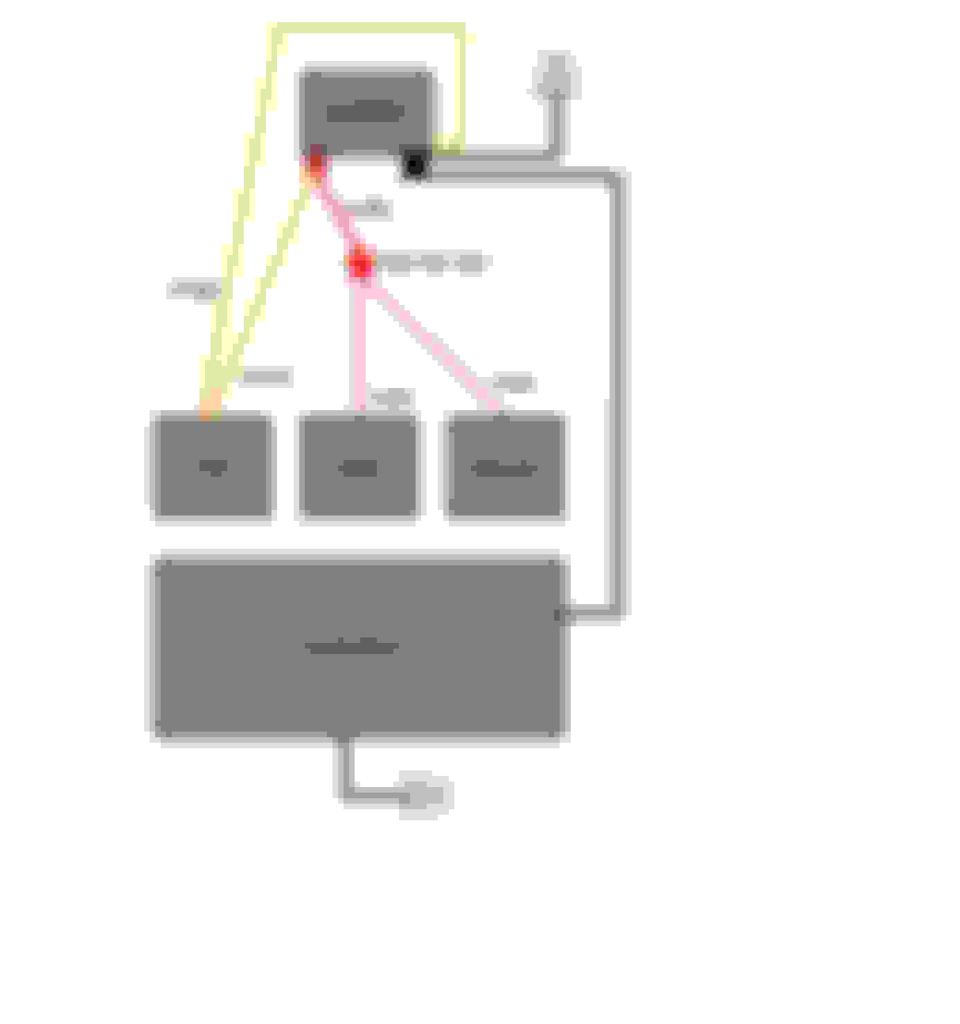
This is not how Electricity actually works...
However for the purposes of a Diagram, Lets say that Power at the PCM is "Clean".
As soon as the "Clean" power hits the Power Distribution Stud...
It gets mixed with the "Dirty" High-Amperage Power (from the starter etc), down the 0 AWG Wire to the Battery.
So instead, we make a direct connection from the PCM to the Battery instead.
...and yes the Battery acts as a massive "Noise Filter".
Last edited by vorteciroc; 09-16-2021 at 06:09 PM.
Now in this altered Diagram, Electricity leaves the Negative Post of the battery and travels down the 10 AWG Black Wire to the PCM.
Through the PCM.
Into the 10 AWG Blue Wire, and back to the Battery without having to pass through any Wires that are passing a High-Amperage.
Thanks @vorteciroc . After your posts last night, I called an old college friend of mine who does electrical engineering as part of his job to ask a few questions (so I don't keep cluttering up this post with them). Here are my notes, which aligns with your guidance:
"Clean" & "Dirty" power and the need for isolation
Newer cars should use fairly standardized power converters (to step down to voltages actually used, like 3.3V or 5V) within their control modules such that they should handle just about anything thrown at them. However, this isn't always the case, particularly the further back you go when auto manufacturers were building their own power conversion components and tightly targeted their use-cases to cut cost/complexity. As such, from an engineering best-practices perspective, it's a good idea to use the battery to isolate "sensitive" circuits from those that can consume high amounts of amperage (like a starter) when uncertain or making a system more fault tolerant.
Why? What's the difference between "T-ing" at the battery post, and at a point a small distance away (e.g. with a splice or buss)?
Ohm's Law, which states that the current through a conductor between two points is directly proportional to the voltage across the two points. I = V/R (I = current in amperes, R = resistance of the conductor in ohms, V = voltage measured across the conductor in volts). When something like the starter consumes high amperage from the battery, if you tied your power together at the starter (like GM did with our cars), you'd measure a low voltage at anything downstream while the starter was cranking. If you instead Tee’d off the conductor between the battery and the starter, you’d see a voltage drop directly related to your distance from the battery (due to Ohm’s law, and that resistance increases the further you are from the power source along the conductor).
Lower gauge wires have less resistance, so they would show a lower amount of voltage drop. While you could use something like a 0AWG cable between the battery and a buss, you’d still see some amount of drop when starting, and the resistance of the buss itself would also come into play. Lowest voltage drop would come from going straight to the battery post.
At this point we need to tie at least 2 circuits, maybe more, direct to the battery post. Would something like the “military style” terminal be good for this?
There are better options that maximize contact patch between the terminal and post. With the military style terminal, only a small ring makes contact with the bolt head and terminal body. Other terminal blocks, typically made for adding sound systems, allow a larger contact patch for several cables and are best paired with appropriately sized ferrules to both maximize contact patch and protect individual wires within the cable from being damaged. While a military style terminal is "good enough" to supply the power to low guage cables, it shouldn't be considered best practice for power delivery.
Military Style Battery Terminal
Better Designed Battery Terminal (Quality may actually be bad... buy good parts)
Last edited by 3.1EyeCandy; 09-18-2021 at 09:16 AM.
I actually use different "Car Audio" type Terminals (similar to what you posted) when I have multiple large Gauge Wires at the Battery.
There are so many options for Terminals like this to chose from.
I have never had the need for the Terminal in the above image, but it is amazing how many options there are.
Nickle Plated Copper or just Copper, will provide the best Connection.
Aluminum and other Materials are a big step down in terms of Conductance.
I try to find Terminals that are at least partially covered...
I would like to try and protect people from an accidental Short across the Battery Terminals.
Sometimes I use these Terminals from KnuKonceptz (just with Two Wires):
But even the Military style Terminals, that you Posted have Covers available:
Even something like this is okay, with a Plastic Cover:
Modern GM Vehicles have a Bussed Electrical Center mounted on top of the Battery.
This is done so that the initial Power Distribution can start right at the Positive Post of the Battery:
DC 12V Circuits can be some of the most rudimentary Circuits that exist.
A basic Series Circuit can be examined by almost anyone and understand Ohm's Law.
Basic Parallel Circuits can be similarly rudimentary.
The Power Distribution Systems in our Vehicles are most always be some variant of complex Series-Parallel/ Parallel-Series Circuits.
Which brings about both benefits and losses.
Regarding Voltage-Drop... We ideally try to isolate and minimize Voltage-Drop and/ or Voltage fluctuation of the Circuits for our sensitive Electronics.
Non-Electronic devices are intended to handle some level of Voltage-Swing (and the Amperage requirements that coincide).
EMF/ EMI or Noise can also be harmful to sensitive Electronics...
Sensors, like Crankshaft Speed, Camshaft Speed, and the VSS all require additional Shielding (via specific Shielded Wire) for protection.
Lastly, the Vehicles Grounding-System is actually the MOST important part of the Vehicle's Wiring System.
Last edited by vorteciroc; 09-17-2021 at 05:58 PM.
The Third-Gen F-Body Positive Power Cables/ Wires should be layed-out in a similar fashion to the Diagram below:
The Negative Power Diagram will follow soon.
Pass-Through Connectors for the Fire-Wall, would be like this:
Similar Boots as in the Post before this Post, can be used here also.
Delphi also offer great (But expensive) Power-Pack 2000 Connectors, and Pass-Through Connectors (Up to 250A Cont.):
Then the more affordable Power-Pack 1000 Series (125A per Terminal).
Make the 0 AWG Cable into Two of the 2 AWG Cable immediately before the Fire-Wall...
and you have a 250A Pass-Through (you can have One of the 0 AWG Cables again, or keep Two of the 2 AWG Cables, at 125A each):
The next Image shows one of the acceptable methods of segregating Ground-Busses.
This is the way that I lay-out Grounding Circuits; and is a mixture of IEEE and SAE Standards.
I am not looking to get into a debate over the different Ground-Busses at this time.
The Diagram below shows the way in which I create 100% trouble-free 12V-Ground Busses:
The Diagram above is layed-out for a Gen-3/ -4 SBC swap, that used "Smart Ignition Coils".
They implement a 5th Terminal, to create a more direct-path for the Spark-Plug Energy to find it Ground Connection.
The exact Science is not as follows, however for the purposes of understanding what the above Diagram shows; follow along.
Instead of the Spark (from the Ignition-Coil, and Ignition-Wire) traveling through the Head and Block...
To the location on the Block where the negative Battery Cable attaches.
We complete the Circuit via a much shorter distance, with all 4 odd-Coils having an addition Ground-Wire attaching to the Corresponding Head.
The Even side is completed in the same fashion.
When done this way, no other circuits should be grounded with a terminal on the Head or Block.
 09-11-2021, 04:09 PM