custom header flanges
 11-11-2019, 08:21 PM
#1
Supreme Member

Thread Starter
custom header flanges
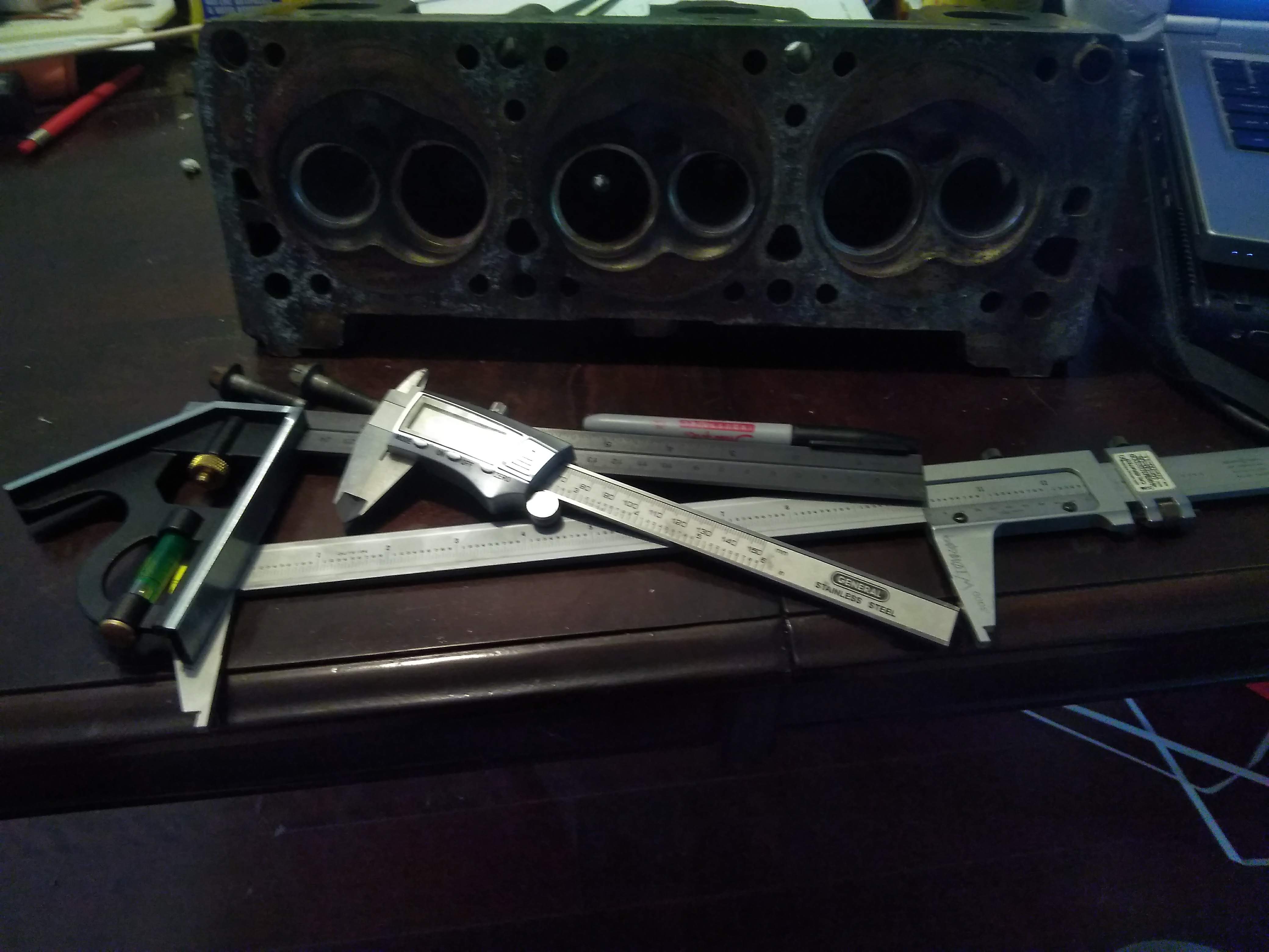
if you're anything like me, you're sick of grossly substandard parts, in this case, I'm working header flanges for the GM 60V6, specifically the LX9 3500.
in my case, I have 2 different flanges, one from British Car Conversions,
https://www.britishcarconversions.co...header-flanges
and one from Stainless Headers
https://www.stainlessheaders.com/pro..._header_flange
here are the flanges on a head...
BCC


stainless headers


The BCC flange absolutely dwarfs the port, it's huge. and the stainless headers flange overlaps the port in some spots... pure garbage, putting it nicely. some of the mismatch on the BCC flange could get taken up by forming the primary tube to the inside of the flange, but it can be seen that it isn't the correct shape either.
The grossly misshapen stainless headers flange isn't good for anything more than a paperweight IMO. you could form the tube to the flange, but then you end up with even more overlap into the port, which would KILL flow.
so, everything is garbage, what do we do? we make our own! how? some simple measuring tools, some time, a spare head, and a cad program.

to start things off, I cleaned the machined surfaces of the head, they need to be free of dirt and surface irregularities that could cause any measurements taken to be off.
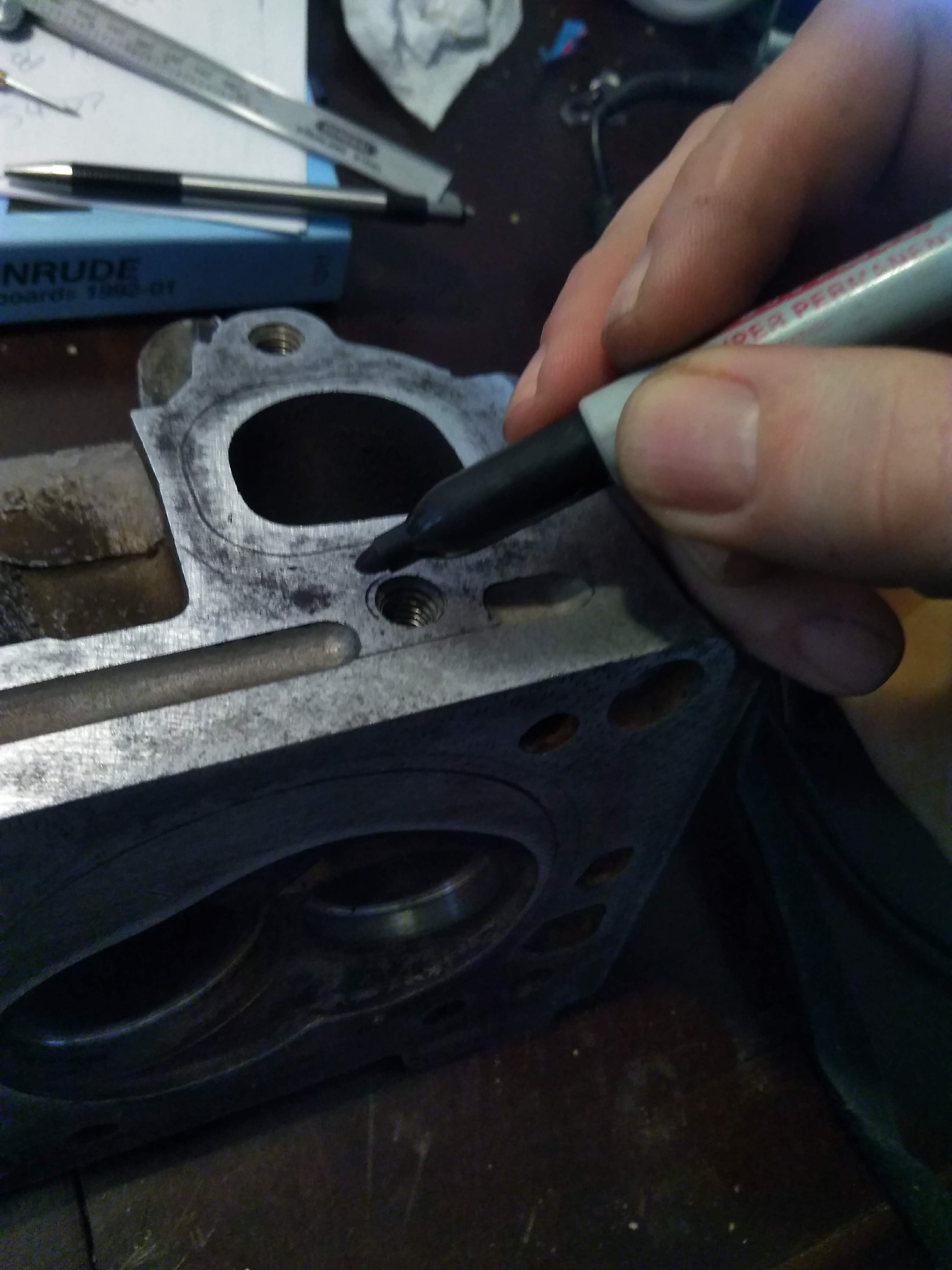
next, on the machined surface the flange will mate too, color in the whole thing with a sharpie, or machinist's blue if you feel like making a huge mess...


using a scribe, make a reference line to work off of. most carpenter's squares have a small scribe in the end, or you can use a sharp piece of tungsten.


when making your reference line, try and choose a machined point, in my case, I used the top of the bolthole for the lower bolt of the flange


in my case, I have 2 different flanges, one from British Car Conversions,
https://www.britishcarconversions.co...header-flanges
and one from Stainless Headers
https://www.stainlessheaders.com/pro..._header_flange
here are the flanges on a head...
BCC


stainless headers


The BCC flange absolutely dwarfs the port, it's huge. and the stainless headers flange overlaps the port in some spots... pure garbage, putting it nicely. some of the mismatch on the BCC flange could get taken up by forming the primary tube to the inside of the flange, but it can be seen that it isn't the correct shape either.
The grossly misshapen stainless headers flange isn't good for anything more than a paperweight IMO. you could form the tube to the flange, but then you end up with even more overlap into the port, which would KILL flow.
so, everything is garbage, what do we do? we make our own! how? some simple measuring tools, some time, a spare head, and a cad program.
to start things off, I cleaned the machined surfaces of the head, they need to be free of dirt and surface irregularities that could cause any measurements taken to be off.
next, on the machined surface the flange will mate too, color in the whole thing with a sharpie, or machinist's blue if you feel like making a huge mess...


using a scribe, make a reference line to work off of. most carpenter's squares have a small scribe in the end, or you can use a sharp piece of tungsten.

when making your reference line, try and choose a machined point, in my case, I used the top of the bolthole for the lower bolt of the flange


 11-11-2019, 08:22 PM
#2
Supreme Member
Thread Starter
Re: custom header flanges
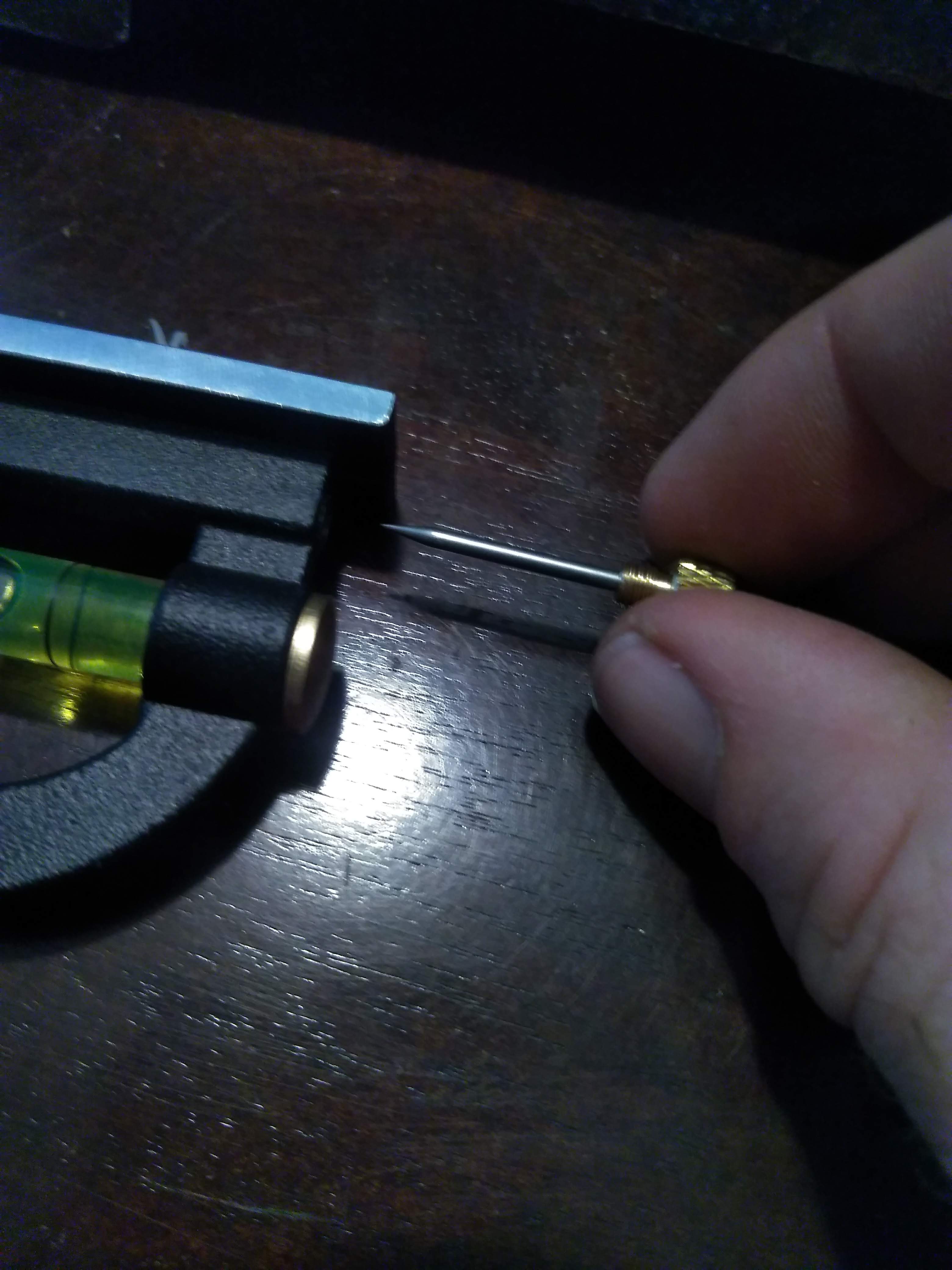
once you have set the reference point, make a nice long scribe line to measure off of. quick tip, if you scribe your line wrong, you can color it back in with the sharpie, and re-scribe, you really don't want to run the scribe hard into the metal if you ever intend on using the head again, in my case, the head I am taking measurements on dropped a valve seat, so it really doesn't matter too much.

Next step is to measure off of your horizontal reference, and make several horizontal lines at even intervals, the more accurately you can do this, the easier your measurements will be, in my case, I made the lines about 2mm apart.

next is to do the same thing on a vertical axis. in this case though, you don't want to use that as your basis for measurement, as it will be over the opening of the port, I measured and scribed a line about 30mm from that point, so that the entire reference point will be on metal.


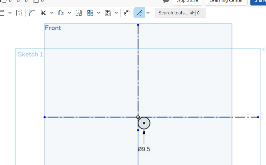
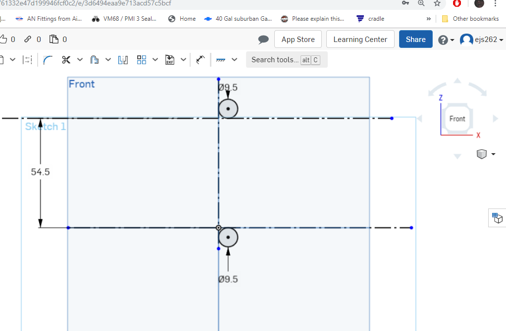
now, I know the axis for my measurements are tangent to the bolthole, so I can measure the diameter of the hole, as well as the distance to the other hole and put the holes in the drawing,


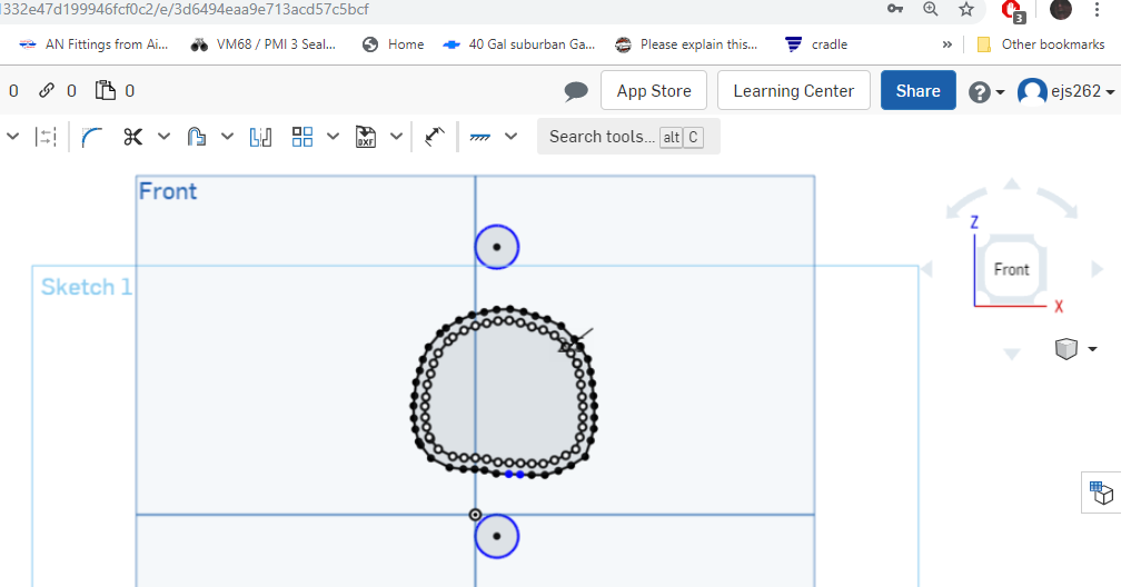
next is the tedious part, we measure the port, from the reference lines, at each point, and plot it in our drawing. the more accurate data points you have, the more exact the flange will be.

once that's done, you can clean up the drawing leaving you with something resembling a port, connect all of the points to close in the shape.

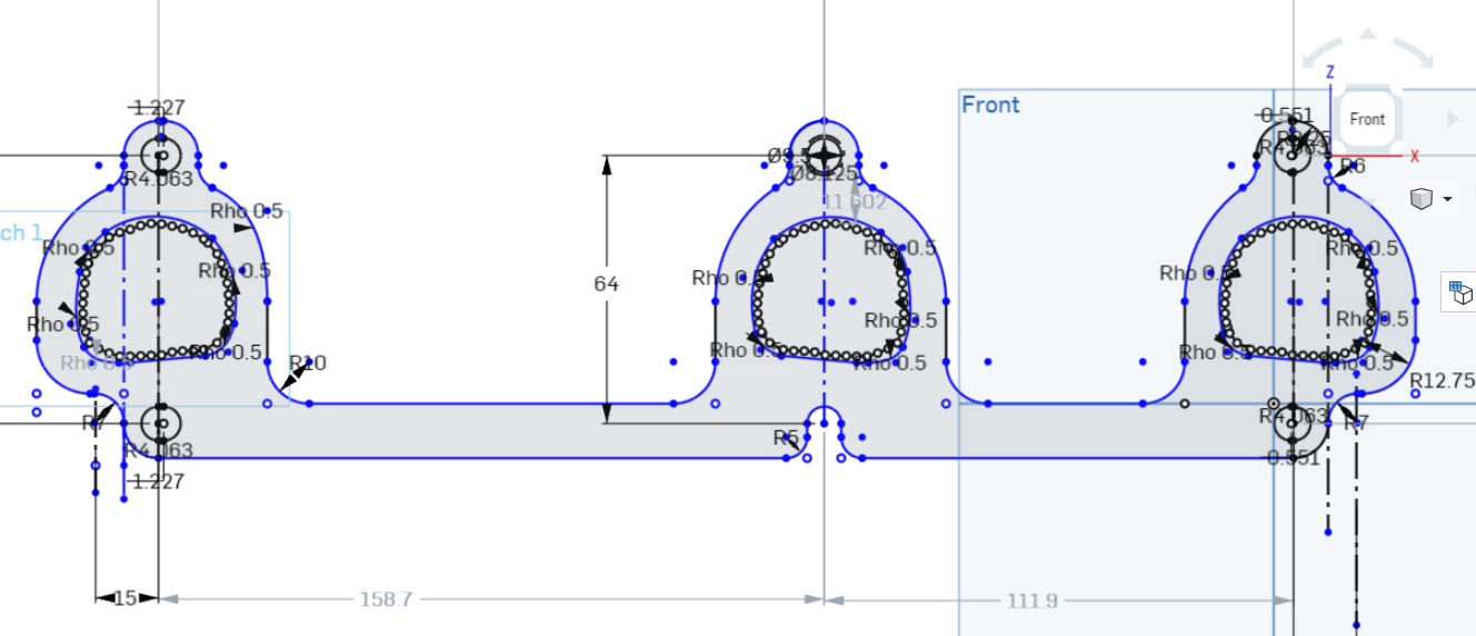
proper port shape and position is important, if the flange overlaps the port, it will be a significant restriction to flow, if the flange is grossly oversized to the port, you'll lose velocity coming out of the port. I oversized my ports by about 10%, this ensures that any variances in the casting won't result in the flange overlapping the port, without being grossly oversize like the BCC flanges. I did this by using the offset tool in OnShape, and offsetting the port by 1.5mm, which creates a new set of points 1.5mm out from their original position, resulting in a port about 3mm wider and taller.


Next step is to measure off of your horizontal reference, and make several horizontal lines at even intervals, the more accurately you can do this, the easier your measurements will be, in my case, I made the lines about 2mm apart.

next is to do the same thing on a vertical axis. in this case though, you don't want to use that as your basis for measurement, as it will be over the opening of the port, I measured and scribed a line about 30mm from that point, so that the entire reference point will be on metal.


now, I know the axis for my measurements are tangent to the bolthole, so I can measure the diameter of the hole, as well as the distance to the other hole and put the holes in the drawing,
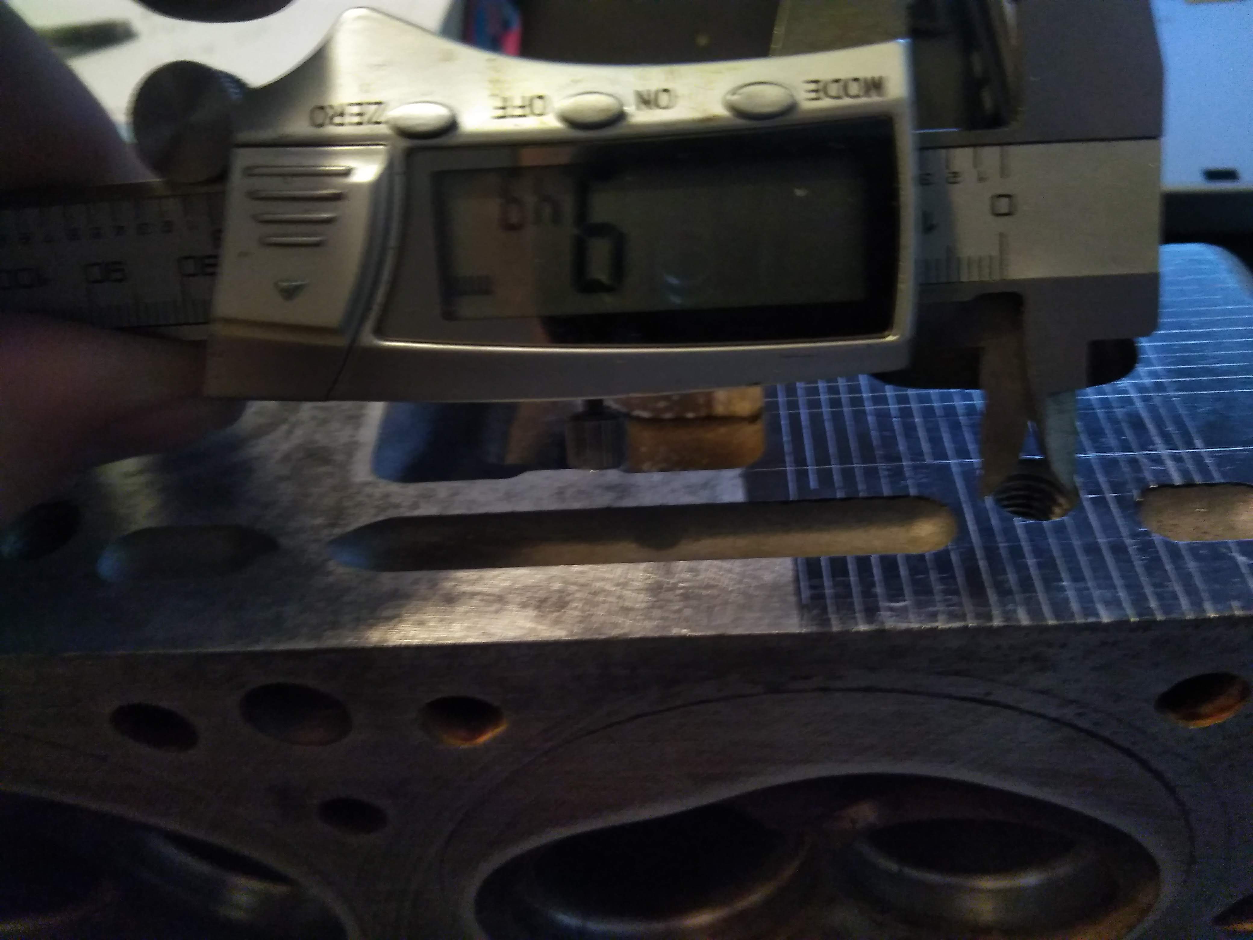

next is the tedious part, we measure the port, from the reference lines, at each point, and plot it in our drawing. the more accurate data points you have, the more exact the flange will be.

once that's done, you can clean up the drawing leaving you with something resembling a port, connect all of the points to close in the shape.

proper port shape and position is important, if the flange overlaps the port, it will be a significant restriction to flow, if the flange is grossly oversized to the port, you'll lose velocity coming out of the port. I oversized my ports by about 10%, this ensures that any variances in the casting won't result in the flange overlapping the port, without being grossly oversize like the BCC flanges. I did this by using the offset tool in OnShape, and offsetting the port by 1.5mm, which creates a new set of points 1.5mm out from their original position, resulting in a port about 3mm wider and taller.
 11-11-2019, 08:22 PM
#3
Supreme Member
Thread Starter
Re: custom header flanges
if you're lucky, all of your ports are identical, and you don't need to remeasure each one, just copy and paste, if you're slightly less lucky. one or more of the other ports are a mirror image of the existing port, and you have to flip them, if you're really unlucky, rinse and repeat for the other ports. either way, the next step is to do the other ports, in my case, I measured the distance between each port, copied, pasted, and then copied, flipped, and pasted. then I traced out what I want the finished flange to look like.

if you're better than me, all of your measurements will be spot on the first time, and you'll be ready to have it laser/water cut and start welding, but a smarter option is to have the flange 3d printed first, to verify fitment.
Oops... I used dimensions for the bolt spacing from an older drawing and assumed I had measured them correctly...

new measurements, new result! now I can easily see the small changes that need to be made, and make those corrections accordingly.

now that you've verified everything is satisfactory, you can have the flanges cut from whatever material you see fit. in my case, I chose 304SS, to match the weld el's I'll be using for my manifold.
something of note, because I am using weld el's with my flanges, they won't be fitted to the inside of the ports like you would normally see with headers. in this case, the port has the same perimeter as a 1.5" OD pipe or tube forming a pipe or tube to that shape may result in the pipe intruding into the gas flow, resulting in poor performance, so enlarging the flange further may be necessary to optimize performance. this technique will likely work in other applications, but will probably not be very effective for OHC engines, as the ports usually aren't in an as easy to measure position. I have hopefully one last revision to print, and I'll be ready to cut the flanges in something a little more permanent.
if you're better than me, all of your measurements will be spot on the first time, and you'll be ready to have it laser/water cut and start welding, but a smarter option is to have the flange 3d printed first, to verify fitment.
Oops... I used dimensions for the bolt spacing from an older drawing and assumed I had measured them correctly...
new measurements, new result! now I can easily see the small changes that need to be made, and make those corrections accordingly.

now that you've verified everything is satisfactory, you can have the flanges cut from whatever material you see fit. in my case, I chose 304SS, to match the weld el's I'll be using for my manifold.
something of note, because I am using weld el's with my flanges, they won't be fitted to the inside of the ports like you would normally see with headers. in this case, the port has the same perimeter as a 1.5" OD pipe or tube forming a pipe or tube to that shape may result in the pipe intruding into the gas flow, resulting in poor performance, so enlarging the flange further may be necessary to optimize performance. this technique will likely work in other applications, but will probably not be very effective for OHC engines, as the ports usually aren't in an as easy to measure position. I have hopefully one last revision to print, and I'll be ready to cut the flanges in something a little more permanent.
The following users liked this post:
NoEmissions84TA (11-12-2019)
11-12-2019, 10:22 AM
#4
Senior Member
Re: custom header flanges
Couldn't you hypothetically, port the head to match the BCC flange and get the benifit of better flow and not have to make your own headers? Seems like an aweful lot of work you're doing for stock heads? What's the gain? Not bagging on you at all, these are honest questions...
11-12-2019, 12:20 PM
#5
Supreme Member
Thread Starter
Re: custom header flanges
Couldn't you hypothetically, port the head to match the BCC flange and get the benifit of better flow and not have to make your own headers? Seems like an aweful lot of work you're doing for stock heads? What's the gain? Not bagging on you at all, these are honest questions...
Valid questions. The heads I'm running are thoroughly ported, and have been proven on a flow bench, porting them to the flange may or may not improve performance. Also, these will be for a turbo manifold made using stainless weld elbows, the ports on the flange are actually larger than. The elbows, they may be able to be formed to fits but that would be way more work than I want.
You're right, it's a lot of work, but I'm also using this as an exercise to build proficiency with the software, and tools. I don't currently own a 3rd Feb, but am looking for a Firebird to do a very custom engine swap into, the engine in question has a very limit market, so projects like this not only will perform better, but also help me develop future, more advanced parts.
11-13-2019, 02:11 AM
#6
Re: custom header flanges
Well, the stainless works flanges... I don't know what they're doing there my guess is that since you said your heads are ported that they were working off a stock port.
The BCC flanges look to be a good match to the ported ports you have. I'm guessing they were cut for the same gaskets that your heads look to be ported to, just with an even margin all the way around the port likely for 2 reasons: 1- traditional headers are built by forcing the tubes into the flanges and then welding around the inside (head side) of the flange and grinding them flat, at that point you'll have made the port smaller on all sides. 2- you want a step up into the header flange to prevent reversion. Some header manufacturers will even list this as a feature. You do not want them to match exactly unless you have anti-reversion steps in the header tubes, and even then.
Either way, in this case, it doesn't appear that you're being fair complaining about **** quality, which is definitly appears to be a problem with a majority of parts.
Honestly, I'm not sure why you did it the way you did.
Since you have a flat flange surface I would have done it the quickest way possible and set that flange surface on a scanner bed and scanned it. Being a V6 of sorts it might fit on a standard scanner bed, but if it didn't you can scan both ends and then overlap the middle of the scans in some image editing software till it lines up perfectly. I think I showed the process here in a thread about making custom alternator brackets based on an existing one and then importing the picture into Sketchup and extending the bracket for a larger alternator case and more adjustment range. I've done the same deal for having Cometic cut me a set of custom head gaskets by setting the head flat down on the bed. You end up with a scan that you did at a specific DPI (for something large 100 or 150 is fine, for something small 300 gives you more detail to work with) and it's fairly easy to import into lots of different software (Cometic wanted DXF, I don't remember why I used Sketchup for the bracket, I typically use Fusion 360 because it runs well on my laptop) and trace the drawing exactly or some software will let you use it as the surface of a 2D sketch that you can extend into a 3D model.
If you didn't have a flat surface to set on a scanner bed I've gotten away with a good camera lens and a tripod. Unless you want to get stuck messing with distortion correction you want a lens that is the equivalent of 50mm or longer on the camera body you're using and you want to keep the object out fo the edges of the picture. Be careful with zoom lenses since they can induce additional distortion. I've used a Nikon DX7100 with either a 35mm prime (the equivalent of 50mm on a DX-format camera) or one of 2 zooms that I have set at something about 2/3 up their zoom range (most zooms are sharpest and have the least distortion somewhere in the range of 1/2-3/4 of their total zoom and f stop in the 8-11 or so range, there are some review sites you can find the information online, and the actual best settings can change with different f-stop settings). Take a picture as flat as you can get it, measure the largest dimensions that you can on it (the bigger the more accurate it will be) and scale the picture so it matches at a set DPI. Then measure the 2 end ports and do any perspective correction that you need to and the rest is the same as with a scan.
There is even smartphone "scanning" software that will do a lot of this for you using your smartphone camera, but except for a couple of emergency "I need this now," situations I can't bring myself to trust some smartphone software for something that I'm going to be doing a lot of work based off of.
Being one that has done a few oddball stuff and likes to play "what if," I'm very curious about what engine you're thinking of swapping? We've played this quite a bit with V6 cars thinking about setups that would result in a super light car with good power and handling. I've considered some really weird ones for a Fiero swap...
The BCC flanges look to be a good match to the ported ports you have. I'm guessing they were cut for the same gaskets that your heads look to be ported to, just with an even margin all the way around the port likely for 2 reasons: 1- traditional headers are built by forcing the tubes into the flanges and then welding around the inside (head side) of the flange and grinding them flat, at that point you'll have made the port smaller on all sides. 2- you want a step up into the header flange to prevent reversion. Some header manufacturers will even list this as a feature. You do not want them to match exactly unless you have anti-reversion steps in the header tubes, and even then.
Either way, in this case, it doesn't appear that you're being fair complaining about **** quality, which is definitly appears to be a problem with a majority of parts.
Valid questions. The heads I'm running are thoroughly ported, and have been proven on a flow bench, porting them to the flange may or may not improve performance. Also, these will be for a turbo manifold made using stainless weld elbows, the ports on the flange are actually larger than. The elbows, they may be able to be formed to fits but that would be way more work than I want.
You're right, it's a lot of work, but I'm also using this as an exercise to build proficiency with the software, and tools.
You're right, it's a lot of work, but I'm also using this as an exercise to build proficiency with the software, and tools.
Since you have a flat flange surface I would have done it the quickest way possible and set that flange surface on a scanner bed and scanned it. Being a V6 of sorts it might fit on a standard scanner bed, but if it didn't you can scan both ends and then overlap the middle of the scans in some image editing software till it lines up perfectly. I think I showed the process here in a thread about making custom alternator brackets based on an existing one and then importing the picture into Sketchup and extending the bracket for a larger alternator case and more adjustment range. I've done the same deal for having Cometic cut me a set of custom head gaskets by setting the head flat down on the bed. You end up with a scan that you did at a specific DPI (for something large 100 or 150 is fine, for something small 300 gives you more detail to work with) and it's fairly easy to import into lots of different software (Cometic wanted DXF, I don't remember why I used Sketchup for the bracket, I typically use Fusion 360 because it runs well on my laptop) and trace the drawing exactly or some software will let you use it as the surface of a 2D sketch that you can extend into a 3D model.
If you didn't have a flat surface to set on a scanner bed I've gotten away with a good camera lens and a tripod. Unless you want to get stuck messing with distortion correction you want a lens that is the equivalent of 50mm or longer on the camera body you're using and you want to keep the object out fo the edges of the picture. Be careful with zoom lenses since they can induce additional distortion. I've used a Nikon DX7100 with either a 35mm prime (the equivalent of 50mm on a DX-format camera) or one of 2 zooms that I have set at something about 2/3 up their zoom range (most zooms are sharpest and have the least distortion somewhere in the range of 1/2-3/4 of their total zoom and f stop in the 8-11 or so range, there are some review sites you can find the information online, and the actual best settings can change with different f-stop settings). Take a picture as flat as you can get it, measure the largest dimensions that you can on it (the bigger the more accurate it will be) and scale the picture so it matches at a set DPI. Then measure the 2 end ports and do any perspective correction that you need to and the rest is the same as with a scan.
There is even smartphone "scanning" software that will do a lot of this for you using your smartphone camera, but except for a couple of emergency "I need this now," situations I can't bring myself to trust some smartphone software for something that I'm going to be doing a lot of work based off of.
I don't currently own a 3rd Feb, but am looking for a Firebird to do a very custom engine swap into, the engine in question has a very limit market, so projects like this not only will perform better, but also help me develop future, more advanced parts.
11-13-2019, 07:40 PM
#7
Supreme Member
Thread Starter
Re: custom header flanges
Well, the stainless works flanges... I don't know what they're doing there my guess is that since you said your heads are ported that they were working off a stock port.
The BCC flanges look to be a good match to the ported ports you have. I'm guessing they were cut for the same gaskets that your heads look to be ported to, just with an even margin all the way around the port likely for 2 reasons: 1- traditional headers are built by forcing the tubes into the flanges and then welding around the inside (head side) of the flange and grinding them flat, at that point you'll have made the port smaller on all sides. 2- you want a step up into the header flange to prevent reversion. Some header manufacturers will even list this as a feature. You do not want them to match exactly unless you have anti-reversion steps in the header tubes, and even then.
Either way, in this case, it doesn't appear that you're being fair complaining about **** quality, which is definitly appears to be a problem with a majority of parts.
The Stainless Headers flanges (Not Stainless Works) are shown above against a stock head, porting would only further exacerbate the problem, as would forming the pipe to the flange and insetting them. the stainless flanges are junk.
The BCC flanges are also against a stock head. you'll notice the ports on the head are canted to one side or the other, and the ports on the flange are not. inserting a pipe like you described would help help with the mismatch, but it doesn't correct the angle change of the port.
there are many factors that play into reversion, and you're right, you don't necessarily want a smooth transition to the port, that being said, you also don't want the port to discharge into a gaping hole.
Honestly, I'm not sure why you did it the way you did.
Since you have a flat flange surface I would have done it the quickest way possible and set that flange surface on a scanner bed and scanned it. Being a V6 of sorts it might fit on a standard scanner bed, but if it didn't you can scan both ends and then overlap the middle of the scans in some image editing software till it lines up perfectly. I think I showed the process here in a thread about making custom alternator brackets based on an existing one and then importing the picture into Sketchup and extending the bracket for a larger alternator case and more adjustment range. I've done the same deal for having Cometic cut me a set of custom head gaskets by setting the head flat down on the bed. You end up with a scan that you did at a specific DPI (for something large 100 or 150 is fine, for something small 300 gives you more detail to work with) and it's fairly easy to import into lots of different software (Cometic wanted DXF, I don't remember why I used Sketchup for the bracket, I typically use Fusion 360 because it runs well on my laptop) and trace the drawing exactly or some software will let you use it as the surface of a 2D sketch that you can extend into a 3D model.
If you didn't have a flat surface to set on a scanner bed I've gotten away with a good camera lens and a tripod. Unless you want to get stuck messing with distortion correction you want a lens that is the equivalent of 50mm or longer on the camera body you're using and you want to keep the object out fo the edges of the picture. Be careful with zoom lenses since they can induce additional distortion. I've used a Nikon DX7100 with either a 35mm prime (the equivalent of 50mm on a DX-format camera) or one of 2 zooms that I have set at something about 2/3 up their zoom range (most zooms are sharpest and have the least distortion somewhere in the range of 1/2-3/4 of their total zoom and f stop in the 8-11 or so range, there are some review sites you can find the information online, and the actual best settings can change with different f-stop settings). Take a picture as flat as you can get it, measure the largest dimensions that you can on it (the bigger the more accurate it will be) and scale the picture so it matches at a set DPI. Then measure the 2 end ports and do any perspective correction that you need to and the rest is the same as with a scan.
There is even smartphone "scanning" software that will do a lot of this for you using your smartphone camera, but except for a couple of emergency "I need this now," situations I can't bring myself to trust some smartphone software for something that I'm going to be doing a lot of work based off of.

Being one that has done a few oddball stuff and likes to play "what if," I'm very curious about what engine you're thinking of swapping? We've played this quite a bit with V6 cars thinking about setups that would result in a super light car with good power and handling. I've considered some really weird ones for a Fiero swap...

Thread
Thread Starter
Forum
Replies
Last Post
kerplunk318
Tech / General Engine
1
08-31-2011 09:53 PM