When you click on links to various merchants on this site and make a purchase, this can result in this site earning a commission. Affiliate programs and affiliations include, but are not limited to, the eBay Partner Network.
My stock CS130 is taking a dump and I'd rather just upgrade to the AD244 Alt especially since I have a good working unit at my disposal. How did you wire it to work? I don't see an adapter harness to go from the stock CS130 male plug to the AD244
Do a search on AD244. A few people have done that conversion... including me.
I'll search when I'm not on my phone but I think I read yours and others already. If I'm not mistaken you guys bought the alternator and it came with the harness adapter. I can't afford the new alternator so I was looking for just an adapter harness. I know about slotting the bolt hole etc.
Your AD244 might use a Metri-Pack 150 connector at the accessory terminals. Part numbers are in Post #4 of this thread, https://www.thirdgen.org/forums/ltx-...lectrical.html
Although you might need some different part number terminals depending on wires sizes in your stock harness. I can fetch those part numbers if you tell me your wire sizes.
I think stock 3rd gen alternator uses a Metri-Pack mixed 150 / 280 type connector, part number 12124898. I do not know the mating connector to build your own adapter harness. The Delphi part drawing likely says but I don't have access to that. If the stock wires will reach the new alternator, you could simply cut off the stock connector from your harness and crimp the new terminals in place and install in new connector.
I see Summit Racing sells a variety of alternator adapter harnesses. I think if you get a harness that can adapt from your stock CS130 to a later CS130D alternator, then that will at least give you the right style of connector to plug into your AD244 alternator. You can re-arrange the wires in the connector if needed.
This is just a guess, but I would not think it is necessary to add a resistor to the harness. The stock CS130 has a similar requirement to "current limit" the I or L terminal, so the necessary resistance is probably already built into your stock harness.
Ideally it would really nice to have all the connector, seal, lock, and terminal part numbers to make our own harnesses. This is a very easy DIY job if we just knew the part numbers to order.
Yep! I'm now leaning on just going to the CS144 instead of trying to figure out all the AD244 stuff
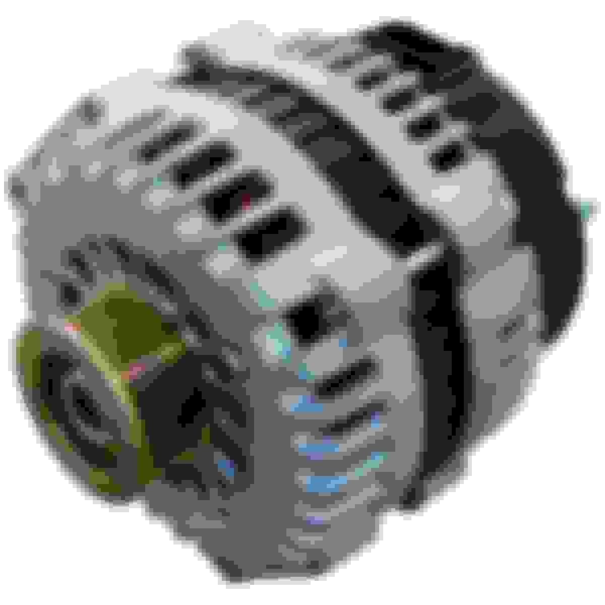
Well, I ordered what I thought was a CS144 Alt from Amazon because I read it was direct plug and play without an adapter needed buuuut this isn't going to work.
That new alternator has the same appearance as what is used on LS1 cars. Even the accessory terminal designations are same. I would take a gander (do people still talk like that? ) that it wires up the same as LS1 and uses the same part number connector shown in Post #4 of this thread, https://www.thirdgen.org/forums/ltx-...ml#post6451619
Sorry, that link I provided is incomplete. It is the minimum necessary to get the alternator working. You have other wires to worry about. And I never updated that post with the connector pinouts.
I don't know how your car is wired but my '88 Firebird service manual shows:
* RED: S terminal. This is a remote voltage "Sense" terminal. Wire comes from a fusible link at starter. It allows alternator to see voltage at battery and charge battery to correct voltage. Run this to the S terminal of your new alternator.
* BRN: F terminal. This is a "Field" terminal. Wire comes from C/H FAN fuse. This is a +12V switched source that turns on alternator regulator and supplies current to the field coil. Run this to the F terminal of your new alternator.
* BRN: L terminal. This is a "Lamp" driver terminal. Wire comes from C100 F8, and it operates the charging indicator light bulb in your dash. Run this wire to the L terminal of your new alternator.
* P terminal. This is a "Phase" terminal and is not used with our cars. Without going into how it works, it was used with mechanical engines (no ECM) to operate a tachometer or engine hour meter, or maybe detect if a belt is thrown (alternator not spinning).
I'm not familiar with automotive alternators in particular so take my advice with a bit of caution, but I don't think both F and L are needed at the same time for alternator to operate. Either will do. This might be why you see people come up with different solutions because there really is more than one way to get the job done. But the F terminal directly feeds the field coil and is the more proper way to turn on the alternator.
L terminal has a maximum allowable current limit (maybe 0.5A or 1.0A, I can't remember exactly), above which the internal circuitry of the alternator will become damaged. This is why you always see a 50 Ohm resistor or an equivalent incandescent light bulb on that circuit. That requirement is already satisfied by the stock gauge panel wiring in your car so there is no need to add a resistor. It's actually best practice to use a blocking diode to prevent reverse current after alternator turns on but that is often overlooked.
Either L and I are the same terminal, or maybe F and I. I'm not sure which is the case without being able to see schematic on the original engineering drawing.
I = "Ignition" terminal. It usually has ability to turn on the alternator from an external switched power source. Sometimes mandatory for alternator to function, sometimes not. All depends on the design of the regulator and how that terminal is wired internally. Somebody that knows these alternators in detail could answer.
I just installed an ad244 220 amp alternator on my car and I'm also using the ICT billet wire harness with the inline resistor. Haven't fired up the car with it yet but should be all kinds of powerful.
I used to have a cs130d alternator that was 175 amp but I'm fairly certain I spun it too fast damaging it. I noticed on my laptop it wouldn't get over 13v while driving and sitting in traffic it dropped below 12v
I think I might just bail on this and just get the CS144 which is supposed to bolt right in and plug right in BUT I'm not even sure which make or model I need to order for a CS144
The Above Post shows both the CS130 Alternator and the AD244 Alternator...
The Connection on each Alternator and the Corresponding Pin-Outs.
And the 2 Different types of Voltage Regulators used: ( "PLFS" and "PLIS").
Including how to make these Connections and the Purpose of these Connections in the Diagram that I created.
Awesome, thanks man! I'm looking now for the square/rectangle female plug like the CS130 so I don't have to cut my harness. The only place that I saw that has that W3030D wants dang near $50 shipped for their jumper harness
Yes, I'm very curious about part number too. I found an alternator plug with a blue seal but not the green seal. And I've not been able to find a mating connector needed to build a jumper harness.
What you guys have seen are all completely Aftermarket...
Some that I have Obtained over the years have been produced on a 3D-Printer.
Terminal Fitment and Retention for all have been highly suspect!
I'm not very wiring savvy and looking at those diagrams, on the CS130 they show the "S" terminal as coming out of the plug and going to the lug on the Alt and my stock setup is not like that. I have the 3 wires from the harness going into the plug and a separate 8GA? wire going from the Alt lug to the POS battery.
They also show only 2 wires on the CS130 but our cars have 3
Which alternator did you decide?? I f you went ad244 buy the harness in the picture and send that wire to switched power and charging lug right to the battery. Done. Or just buy a stock replacement and plug it in and go
Technically the alternator will work with just 1 of those accessory wires connected, but it will work better with all 3 original wires from the car.
* Your stock BRN wire for L terminal should be used only for the dash warning light. Yes, technically it could be used to turn on the alternator, but the problem is the gauge pod wiring in our cars just isn't reliable enough for critical functions like running an alternator. I used this wire (and only this wire) with my car and I had all kinds of trouble with the alternator turning off intermittently. Connection to gauge pod is too flaky. Use it for warning light, but don't depend on it for anything else.
* The GM engineers knew this and that's why they gave you the stock BRN wire to F terminal. It's a reliable piece of wiring from the C/H FAN fuse that you can use to turn on the alternator. Use it. Absolutely use it. Whether the new alternator turns on using L terminal, F terminal, I terminal... whatever they call it.... this is the wire you use to do that. Now keep in mind this wire does not have a resistor in the circuit, so if your new alternator requires a resistor then you'll have to add an appropriate resistor.
* The GM engineers did you one more favor by laying a RED wire in the stock harness for S terminal. LS1 cars don't have this. It's not necessary for alternator to operate, but it improves how the alternator operates. The wire is already laid in your stock harness so use it. It will improve life of your battery by prioritizing charging voltage at battery over all else.
I'm not very wiring savvy and looking at those diagrams, on the CS130 they show the "S" terminal as coming out of the plug and going to the lug on the Alt and my stock setup is not like that. I have the 3 wires from the harness going into the plug and a separate 8GA? wire going from the Alt lug to the POS battery.
They also show only 2 wires on the CS130 but our cars have 3
If you are looking at the "Desert Dog's" Diagram....
It is partially incorrect.
The Red Wire from the "S" Terminal to the Charge Stud is WRONG.
However, the Typed/ Labeled info, stating Connect "S" Terminal to Battery is Correct.
This is why I started producing my own Diagrams, as show lower in the Post.
What about sending the S terminal to a power distribution block?? I don't have mine wired in anywhere but I've been reading more into it lately. Sounds like it's a good idea for the life and durability of the battery
No, you want the "S" Terminal (remote SENSING terminal) to Directly connect to the battery for the Circuit to do it's job best.
The Purpose of this Circuit is to:
-See the drop in Voltage at the Battery when the Charging System is being stressed (let's say 12.305 Volts)...
Compared to the Voltage being output at the Alternator Charging Post (let's say 14.510 Volts).
If within the Limitations of the Charging System... The Alternator to try to adjust/ Raise the Output.
Again, pardon my ignorance but when you say the red "S" wire from my stock plug should go directly to the battery, do you mean it should go do the "S" on the AD244 like others have mentioned?
(The "S" terminal/ Remote Voltage Sense Circuit)
The Voltage Regulators used in the AD244 Alternators do not really need/ nor benefit from the Sense Wire.
As Voltage Regulator Technology improved over the years with the I/F Terminal being connected to the PCM...
There is really no need for the "S" Terminal to be connected anymore.
As such you can see:
-The terminal itself was down-sized to a lower Ampacity Terminal.
-The Wire used for said Terminal was also down-sized.
If you refer back to my "Actually Correct" Diagram, and not that "Desert Dog" Diagram...
You can see that I stated use of the "S" Terminal is Optional (Shown again below):
Last edited by vorteciroc; 12-07-2023 at 08:56 PM.
For the New (at that time) Alternators that use the Electrical Connector (like the AD244) We (Delphi) Designed and Produced multiple Variation of the Connector that use less than 4 Terminals.
Most commonly a Single Terminal "L" Connector and a Dual Terminal "L" and the "I/ F" Connector.
This information has been already collected and very nicely presented by the ever Diligent @QwkTrip ...
In His "Part numbers of common electrical connectors with LS engine swaps" Mega-Thread.
Link to Thread below: HYPERLINK
Here are some Images of His Thread below:
Electrical Connector Body Part Numbers (as shown above in Images) are:
-"L" Terminal Only: 12186566.
-"L" and the "I/ F" Terminals Only: 15355066.
What's the max safe shaft rpm for the ad244?? I run a 10% underdrive crank pulley and using my motion raceworks 3.5" Alternator pulley I get no charging at idle. But if I run a stock size alt pulley I'm afraid of spinning too fast and damaging the Alternator. Engine shifts around 6800-7000 rpm. Idle is set at 800 but can move that up to 900 if need be
I don't know the actual specification, but pretty much anything this small will go at least 10K rpm continuous (pulley speed). A lot of these compact alternators can handle 13K rpm continuous. Bearings probably won't tolerate more than 18K rpm. The higher the speed the more accelerated the brush wear.
A lot of alternators are designed to have 1/3 output by 2K rpm, and pretty much be at peak output somewhere between 6K - 7K rpm.
I don't know the actual specification, but pretty much anything this small will go at least 10K rpm continuous (pulley speed). A lot of these compact alternators can handle 13K rpm continuous. Bearings probably won't tolerate more than 18K rpm. The higher the speed the more accelerated the brush wear.
Yes I've read they need to be kept below 18k rpm, I guess I'm trying to find a happy medium between high rpm use and idle. It's a little frustrating seeing no charging happening at idle. I think I might try Hawks 2.85" pulley and see how that works. So with my ATI at 6.78 / 2.85 = 2.38 ratio * 850 idle = 2022 shaft rpm @7000 rpm 16,660. That's well below 18k but it's the idle I'm more concerned about. If I bumped idle to 900 rpm = 2142 shaft speed. If I went with a 2.75 pulley I'd be 2219 @900 rpm 17,258 @7000. It's been hard to find solid info about these units besides amp output
Using a stock pulley is how my cs130d stopped charging I spun that sucker to like 19-20k. It slowly started dropping then stopped altogether
Last edited by thatsupnow; 12-08-2023 at 11:28 PM.
I have a hot idle at 1050 rpm, gives me better off-idle throttle response. You would never guess by sound, it still has some chop.
Do you have access to two clamp-on current probes that you could place over the battery cables? If so, then I can explain how to measure your charging capacity.
If not, then you can hunt the alternator speed you need by setting a high idle and gradually lowering engine speed. The voltmeter will drop immediately when battery goes from charging state to discharging state (alternator output is exceeded). Then you can calculate shaft speed to know what is the bottom floor.
Turn on all common loads when you run that test.... Lights, wipers, HVAC blower, make sure radiator fans are running. Defrost is considered intermittent and you don't have to cover that load, but it certainly is nice if you can. Battery charging is also a load and could be very high depending on battery SOC, so make sure your battery is fully charged when you do this test. (If you have current probes then battery SOC won't matter.)
Don't run that test from a low speed going up. You might walk past the floor and not even know it. Reason is system voltage recovers more slowly when going from a discharging state to charging state. But voltage will drop immediately when alternator capacity is exceeded (high speed going down).
Hmm ? I don't have a clamp on current probe but I could ask around and maybe borrow one. Otherwise I'll just hunt the alternator speed with a high idle. Start high and drop in 50 rpm steps. Would current probes make finding this more accurate??
Would current probes make finding this more accurate??
A slight bump in idle speed might go a long ways. It's a very easy and practical test, I would try that first.
Current probes will allow you to truly understand how much current the alternator can deliver, what is your system electrical load, and how much extra charging capacity you have for battery charging. And if alternator can't keep up then you can measure the battery discharge rate. Ideally you want to be able to cover electrical loads and have an extra 10A or more available for battery charging.
One of the current probes has to be bi-directional, meaning you can tell the difference between battery charging vs. discharging. The current probes will need about 250A - 300A range (enough to measure alternator full output). I wouldn't spend money on this though unless you're really at the end of your rope with this issue.
Also, alternator output current will drop as the alternator heats up. It take about 5 minutes run time for temperature to stabilize and get consistent results.
A slight bump in idle speed might go a long ways. It's a very easy and practical test, I would try that first.
Current probes will allow you to truly understand how much current the alternator can deliver, what is your system electrical load, and how much extra charging capacity you have for battery charging. And if alternator can't keep up then you can measure the battery discharge rate. Ideally you want to be able to cover electrical loads and have an extra 10A or more available for battery charging.
One of the current probes has to be bi-directional, meaning you can tell the difference between battery charging vs. discharging. The current probes will need about 250A - 300A range (enough to measure alternator full output). I wouldn't spend money on this though unless you're really at the end of your rope with this issue.
Agreed I'll try bumping the idle up a bit first before going further. I don't have a huge load on the system I've got 2 340 fuel pumps, 2 Derale pusher fans, remote transmission cooler with 10" fan. No heat or AC system. I should have plenty of charging power.
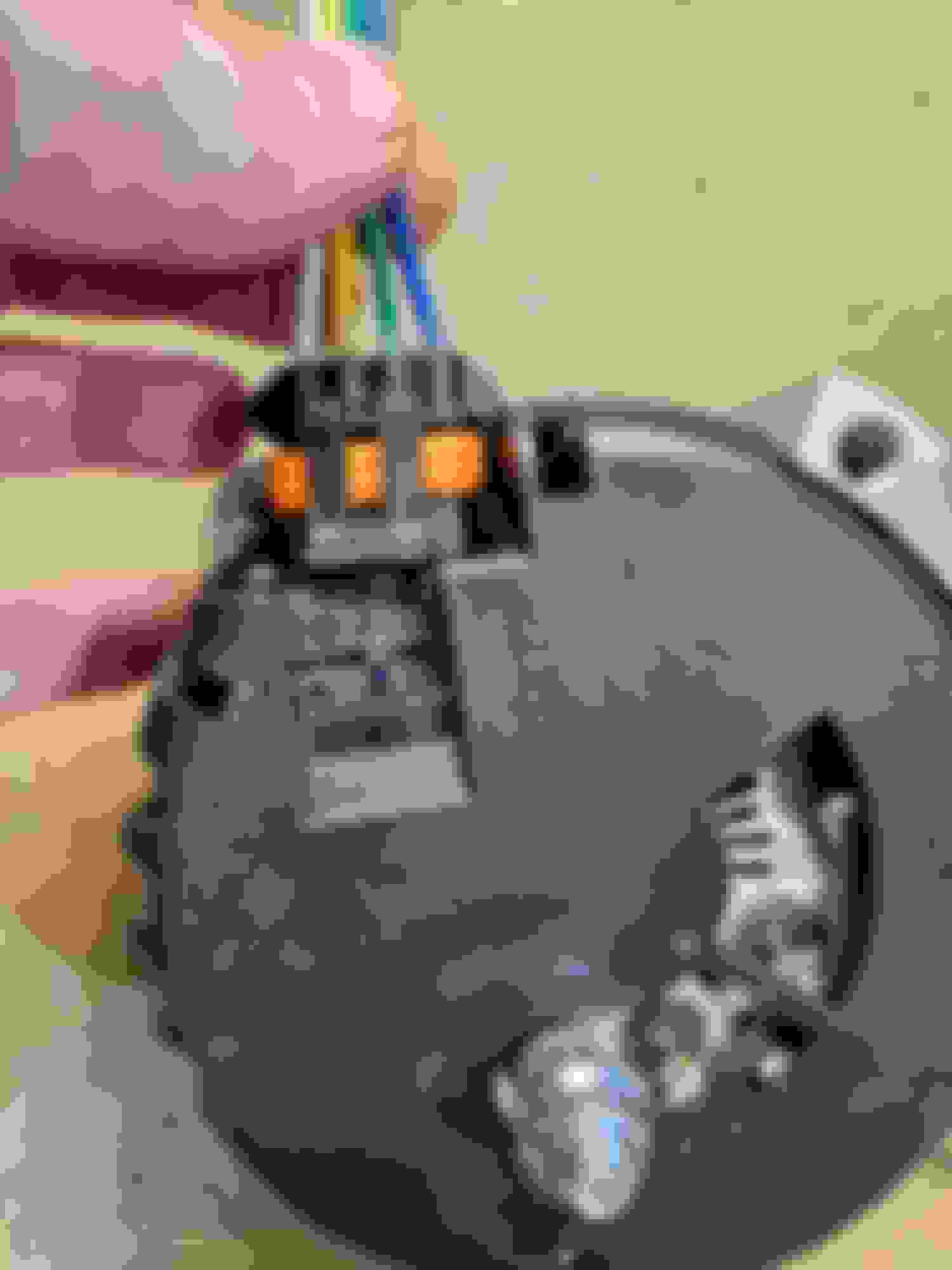
So, I went ahead and bought a stock replacement alternator and completely forgot I ordered a jumper harness. It showed up today and it might actually work as intended. The company wrote "As long as the L terminal on the alternator is able to receive 5+ volts it should be able to operate the alternator. This would be from a switched 12v circuit or a key on/off system." So I went out and looked at the setup. The "L" wire would line up to the factory wiring where the "L" is on the body harness.
Yeah the quality of that plug is not nice haha. I'm still going over this thread trying to understand all of this. It appears this will work but I'm wondering if I need to cut out the other wires or if I can just leave that jumper harness as-is and plug her in and go.
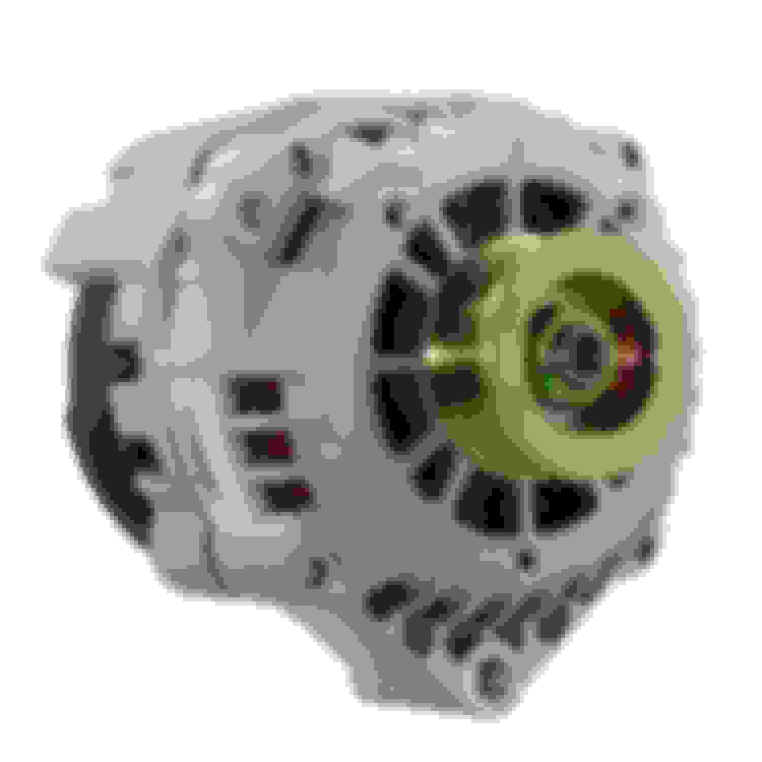
Well I am dumb. This whole time I was typing AD244 because that is what I removed from my 2003 Sierra. I actually bought a CS130D thinking it was an AD244. I got it installed just now but would I be able to just use this jumper plug as it is or do I need to modify it? Here is the actual Alternator I bought:
Aaand that harness is junk. I hooked it up and the S is on the S and with a new alternator I am getting 12.7 volts straight to battery, ignition off. I start the car and test and it goes down to 12.3V so I even tried an AD244 alternator I took off of my 2003 truck. I know its good as its been tested. Exact same thing. Its 12.7 key off and running drops to 12.3v
Aaand that harness is junk. I hooked it up and the S is on the S and with a new alternator I am getting 12.7 volts straight to battery, ignition off. I start the car and test and it goes down to 12.3V so I even tried an AD244 alternator I took off of my 2003 truck. I know its good as its been tested. Exact same thing. Its 12.7 key off and running drops to 12.3v
I give up
Stop buying that crap then bud. All you need to do is send 12v with an inline resistor the L terminal on the alternator and you'll be charging. Simple as can possibly be. Unless you want to keep wasting your time??
Stop buying that crap then bud. All you need to do is send 12v with an inline resistor the L terminal on the alternator and you'll be charging. Simple as can possibly be. Unless you want to keep wasting your time??
Tell me like I'm 5 and have a learning disability. Looking back in this thread, concerning my stock wiring for the Alt:
* BRN: F terminal. This is a "Field" terminal. Wire comes from C/H FAN fuse. This is a +12V switched source that turns on alternator regulator and supplies current to the field coil. Run this to the F terminal of your new alternator.
So I can cut my plug off, tape off the other 2 wires and run my factory Brown wire to the L on the CS130D/AD244 with an inline resistor then run the thicker wire from the stud on the back of the CS130D/AD244 to the battery and I am good?
I went thru the same thing with mine and got annoyed of all the experts giving 100 different ways of doing the same thing. There's a picture of the connector that plugs into the alternator. The terminal with no wire terminal B on the connector(which is L on alternator) is where your switched +12v with an inline resistor will go. Then a thick wire from the stud to the battery. I made you a little picture too
Ah ha! Ok I follow you I think. I don't have crimpers for those terminals but I can probably buy this Painless plug and just depin the pink wire. The B cavity already has a brown wire too so thats cool.
 11-25-2023, 11:24 AM


 ) that it wires up the same as LS1 and uses the same part number connector shown in Post #4 of this thread, https://www.thirdgen.org/forums/ltx-...ml#post6451619