When you click on links to various merchants on this site and make a purchase, this can result in this site earning a commission. Affiliate programs and affiliations include, but are not limited to, the eBay Partner Network.
Ah ha! Ok I follow you I think. I don't have crimpers for those terminals but I can probably buy this Painless plug and just depin the pink wire. The B cavity already has a brown wire too so thats cool.
That should work but I used this one from ict billet
I saw that on Amazon. Is the resistor the correct one? And I saw that its super long. If I cut it down, is the resistor located close to the plug? If not I can just loop it and wire loom it to hide it.
I saw that on Amazon. Is the resistor the correct one? And I saw that its super long. If I cut it down, is the resistor located close to the plug? If not I can just loop it and wire loom it to hide it.
Yea the resistor is close to the plug so you can cut off whatever isn't needed
You don't need a resistor, your car already has a resistor in the stock L terminal circuit as I explained earlier.
And don't depend on your stock L terminal circuit for the only way to turn on the alternator as I explained earlier.
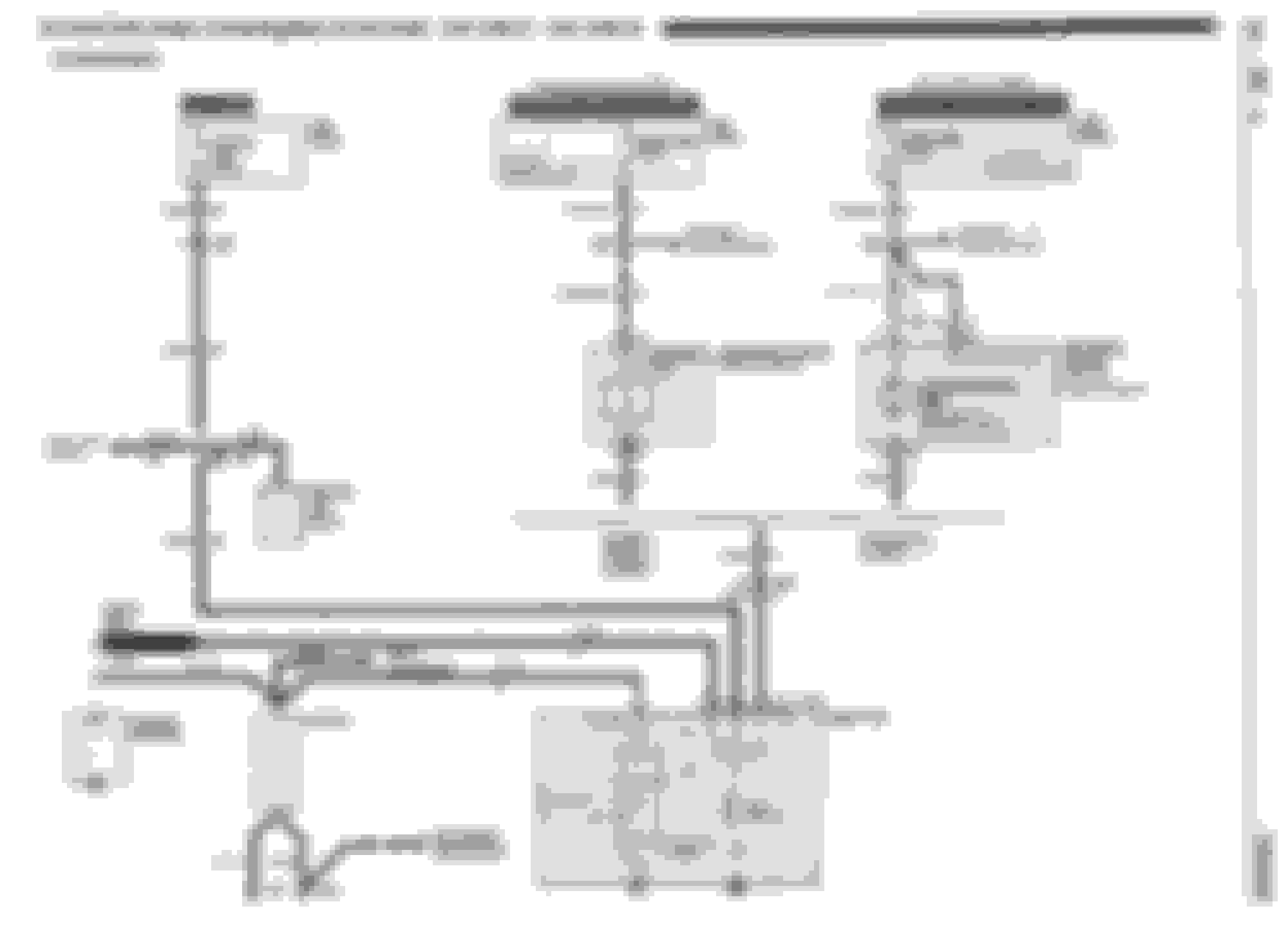
* RED: S terminal. This is a remote voltage "Sense" terminal. Wire comes from a fusible link at starter. It allows alternator to see voltage at battery and charge battery to correct voltage. Run this to the S terminal of your new alternator.
* BRN: F terminal. This is a "Field" terminal. Wire comes from C/H FAN fuse. This is a +12V switched source that turns on alternator regulator and supplies current to the field coil. Run this to the F terminal of your new alternator.
* BRN: L terminal. This is a "Lamp" driver terminal. Wire comes from C100 F8, and it operates the charging indicator light bulb in your dash. Run this wire to the L terminal of your new alternator.
* P terminal. This is a "Phase" terminal and is not used with our cars. Without going into how it works, it was used with mechanical engines (no ECM) to operate a tachometer or engine hour meter, or maybe detect if a belt is thrown (alternator not spinning).
I'm not familiar with automotive alternators in particular so take my advice with a bit of caution, but I don't think both F and L are needed at the same time for alternator to operate. Either will do. This might be why you see people come up with different solutions because there really is more than one way to get the job done. But the F terminal directly feeds the field coil and is the more proper way to turn on the alternator.
Oh I thought you were essentially saying this in your last bolded comment here. Basically, F or L and F would be proper? If so, I think what is up above would be the correct orientation.
You don't need a resistor, your car already has a resistor in the stock L terminal circuit as I explained earlier.
And don't depend on your stock L terminal circuit for the only way to turn on the alternator as I explained earlier.
More than one way to skin a cat tho. The entire alternator thing on forums is a he said she said thing and it gets annoying when you're trying all these ways to get the alternator to charge but for whatever reason isn't working.
I ended going to an automotive electrical shop and they said using the L terminal is just fine and that's what I've been using the entire time with zero issues, charges at 14.4v all day. I'm just trying to find the right pulley to not spin the thing too fast
Aaand that harness is junk. I hooked it up and the S is on the S and with a new alternator I am getting 12.7 volts straight to battery, ignition off. I start the car and test and it goes down to 12.3V so I even tried an AD244 alternator I took off of my 2003 truck. I know its good as its been tested. Exact same thing. Its 12.7 key off and running drops to 12.3v
I give up
This means the alternator never turned on.
Is this the same thing your stock alternator started doing when you began doing all this? Did you have the stock alternator bench tested?
I'm kind of wondering if all your many alternators are fine and the real problem is the wiring in your car.
Oh I thought you were essentially saying this in your last bolded comment here. Basically, F or L and F would be proper? If so, I think what is up above would be the correct orientation.
Yes, you can get the alternator to turn on using alternator L or F terminal. That is true.
L terminal requires a resistor. F terminal does not.
However.... The stock wiring in your car for L-terminal is not such a lovely design and should not be depended on for such a critical function. It goes through the sorry excuse for a connector behind the gauge pod. If you depend on the gauge pod for alternator to function then you're going to be sorry some day when alternator doesn't function. You can still use it for purpose of a warning light (like its intended function as your car was designed).
The F-terminal wiring in your car is literally dedicated to turning on an alternator. Why not use it? That's what it is there for.
If you were starting with no harness at all then you could lay new wire to a fused power source and do whatever you want. But you already have wiring in your car with pro's and con's, and you don't want the con's biting you in the derriere in the future.
Tell me like I'm 5 and have a learning disability.
1. Look at me and listen, young man. (you said 5 years old )
2. Land your wires,
F goes to F
L goes to L
S goes to S
3. Do not add any resistors. Just land the wires. Done.
Not only will everything behave properly like stock, but it is by far the EEEEEEEEASIEST thing to do. Do you really want to graft in resistors that are not necessary???
Note: there are two Different Types of Voltage Regulators used.
-PLIS.
-PLFS.
The Information below is directly taken from early Documents and an Engineer's Updates in the GM Engineering Database.
The functions of the terminals are as follows:
Notes:
Alternator will have either an �F� terminal or an �I� terminal, but not both.
If the alternator has an �F� terminal (i.e. no "I" terminal):
It must be excited by the L terminal.
When exciting via the L terminal, there must be some resistance in the circuit (bulb and/or resistor) or a short circuit will be created.
If no alternator warning lamp is desired, a 470 Ohm resistor is used.
If an alternator warning lamp is used, a resistor should still be used, in parallel with the lamp. This is so that the bulb burning out does not prevent current flow and therefore alternator excitation.
If the alternator has an �I� terminal:
You can use this I terminal to excite the alternator, whether or not you are using an alternator warning lamp (i.e. whether or not anything is connected to terminal L).
Terminal �I� has a built-in internal resistor to prevent a short circuit when connected to the excitor wire. Therefore, you can connect the ignition switch to terminal �I� using an excitor wire with or without a resistor in series.
If you do not have or do not wish to install an alternator warning lamp, you can excite the alternator by connecting the ignition switch to terminal �I� using an excitor wire with or without a resistor in series.
If you do have an alternator warning lamp connected to terminal �L�, you can still connect the the ignition switch to terminal �I� using an excitor wire with or without a resistor in series as a backup method of exciting the alternator. This is good practice as this type of redundancy enhances reliability.
Wiring
PLFS-type
Mandatory connections:
1) Connect the alternator output terminal (B or Bat) to the Battery + terminal or a terminal on the starter motor that also connects to the battery + terminal.
2) Connect the L terminal to a source of switched ignition power through an indicator lamp wired in series. Also connect a 470 Ohm resistor in parallel with the indicator lamp so that if the bulb burns out, the alternator will still be excited.
3) Ensure there is a good ground connection between the bare alternator case, install a dedicated ground wire to the alternator's ground terminal (if it has one).
Crucial connections:
4) Strictly speaking, the alternator will work with only the three wiring connections listed above, but I consider it crucial for good performance that you also wire up the remote voltage sensing terminal. To do this, connect the S terminal to the vehicle Battery. If the S remote voltage sensing terminal is not connected, the voltage regulator will revert to internal sensing of the alternator output terminal voltage - with all the limitations that brings. You will see some alternators wired with a short jumper wire from the S terminal directly to the battery connection at the back of the alternators, but this is neither the proper method for remote voltage sensing nor necessary for internal sensing - do it properly or leave it out.
Optional connections:
5) If you have an external device such as a tachometer, hourmeter, or other device, it may be connected to terminal P. Connect the device in the manner specified by the manufacturer of the device.
This is a diagram of such a CS-series, PLFS alternator wired using terminals L, S, and BAT.
PLIS-type
Mandatory connections:
1) Connect the alternator output terminal (B or Bat) to the Battery + terminal or a terminal on the starter motor that also connects to the battery + terminal.
2) Connect the L terminal to a source of switched ignition power through an indicator lamp wired in series. Also connect a 470 Ohm resistor in parallel with the indicator lamp so that if the bulb burns out, the alternator will still be excited.
3) Connect the I terminal to a source of switched ignition power, or through a 470 Ohm resistor wired in series.
4) Ensure there is a good ground connection between the bare alternator case, install a dedicated ground wire to the alternator's ground terminal (if it has one).
Crucial connections:
5) Strictly speaking, the alternator will work with only the three wiring connections listed above, but I consider it crucial for good performance that you also wire up the remote voltage sensing terminal. To do this, connect the S terminal to the vehicle Battery. If the S remote voltage sensing terminal is not connected, the voltage regulator will revert to internal sensing of the alternator output terminal voltage - with all the limitations that brings. You will see some alternators wired with a short jumper wire from the S terminal directly to the battery connection at the back of the alternators, but this is neither the proper method for remote voltage sensing nor necessary for internal sensing - do it properly or leave it out.
Optional connections:
6) If you have an external device such as a tachometer, hourmeter, or other device, it may be connected to terminal P. Connect the device in the manner specified by the manufacturer of the device.
This is a diagram of such a CS-series, PLIS alternator wired using terminals L, S, I, and BAT.
And does the LS1 F-body alternator (2000 Camaro) have yet a different regulator?
Reason I ask is because labels are PLFS and I was told by the regulator engineer at Remy (as they were called at the time) that I can excite it via the F terminal. And that is what I do in my car that is LS swapped. I don't even have L terminal hooked up.
Note: there are two Different Types of Voltage Regulators used.
-PLIS.
-PLFS.
The Information below is directly taken from early Documents and an Engineer's Updates in the GM Engineering Database.
The functions of the terminals are as follows:
Notes:
Alternator will have either an �F� terminal or an �I� terminal, but not both.
If the alternator has an �F� terminal (i.e. no "I" terminal):
It must be excited by the L terminal.
When exciting via the L terminal, there must be some resistance in the circuit (bulb and/or resistor) or a short circuit will be created.
If no alternator warning lamp is desired, a 470 Ohm resistor is used.
If an alternator warning lamp is used, a resistor should still be used, in parallel with the lamp. This is so that the bulb burning out does not prevent current flow and therefore alternator excitation.
If the alternator has an �I� terminal:
You can use this I terminal to excite the alternator, whether or not you are using an alternator warning lamp (i.e. whether or not anything is connected to terminal L).
Terminal �I� has a built-in internal resistor to prevent a short circuit when connected to the excitor wire. Therefore, you can connect the ignition switch to terminal �I� using an excitor wire with or without a resistor in series.
If you do not have or do not wish to install an alternator warning lamp, you can excite the alternator by connecting the ignition switch to terminal �I� using an excitor wire with or without a resistor in series.
If you do have an alternator warning lamp connected to terminal �L�, you can still connect the the ignition switch to terminal �I� using an excitor wire with or without a resistor in series as a backup method of exciting the alternator. This is good practice as this type of redundancy enhances reliability.
Wiring
PLFS-type
Mandatory connections:
1) Connect the alternator output terminal (B or Bat) to the Battery + terminal or a terminal on the starter motor that also connects to the battery + terminal.
2) Connect the L terminal to a source of switched ignition power through an indicator lamp wired in series. Also connect a 470 Ohm resistor in parallel with the indicator lamp so that if the bulb burns out, the alternator will still be excited.
3) Ensure there is a good ground connection between the bare alternator case, install a dedicated ground wire to the alternator's ground terminal (if it has one).
Crucial connections:
4) Strictly speaking, the alternator will work with only the three wiring connections listed above, but I consider it crucial for good performance that you also wire up the remote voltage sensing terminal. To do this, connect the S terminal to the vehicle Battery. If the S remote voltage sensing terminal is not connected, the voltage regulator will revert to internal sensing of the alternator output terminal voltage - with all the limitations that brings. You will see some alternators wired with a short jumper wire from the S terminal directly to the battery connection at the back of the alternators, but this is neither the proper method for remote voltage sensing nor necessary for internal sensing - do it properly or leave it out.
Optional connections:
5) If you have an external device such as a tachometer, hourmeter, or other device, it may be connected to terminal P. Connect the device in the manner specified by the manufacturer of the device.
This is a diagram of such a CS-series, PLFS alternator wired using terminals L, S, and BAT.
PLIS-type
Mandatory connections:
1) Connect the alternator output terminal (B or Bat) to the Battery + terminal or a terminal on the starter motor that also connects to the battery + terminal.
2) Connect the L terminal to a source of switched ignition power through an indicator lamp wired in series. Also connect a 470 Ohm resistor in parallel with the indicator lamp so that if the bulb burns out, the alternator will still be excited.
3) Connect the I terminal to a source of switched ignition power, or through a 470 Ohm resistor wired in series.
4) Ensure there is a good ground connection between the bare alternator case, install a dedicated ground wire to the alternator's ground terminal (if it has one).
Crucial connections:
5) Strictly speaking, the alternator will work with only the three wiring connections listed above, but I consider it crucial for good performance that you also wire up the remote voltage sensing terminal. To do this, connect the S terminal to the vehicle Battery. If the S remote voltage sensing terminal is not connected, the voltage regulator will revert to internal sensing of the alternator output terminal voltage - with all the limitations that brings. You will see some alternators wired with a short jumper wire from the S terminal directly to the battery connection at the back of the alternators, but this is neither the proper method for remote voltage sensing nor necessary for internal sensing - do it properly or leave it out.
Optional connections:
6) If you have an external device such as a tachometer, hourmeter, or other device, it may be connected to terminal P. Connect the device in the manner specified by the manufacturer of the device.
This is a diagram of such a CS-series, PLIS alternator wired using terminals L, S, I, and BAT.
Thanks for the info, sir! I will have to read it a few times to make sure I understand all of the functions. So it basically says the stud on the back goes to the battery AND the thicker (10GA?) "S" wire goes to the battery as well?
OOOOOOHHHHH! I see my confusion! I was looking at an '88 Firebird service manual and saw "F" for the BRN wire label at the alternator. But the alternator itself is a PLIS regulator.... I totally missed that!
The BRN "F" wire is actually an "I" wire coming from a switched power source (C/H-FAN fuse). Schematic is kind of misleading if you don't know how to interpret that F/I label switch-a-roo at the alternator.
Sorry, Nutro, I was trying my best to help and didn't mean to cause confusion. My instructions were actually entirely correct for a PLIS type regulator, it's just that the original "F" BRN wire in your car (that's actually an "I" wire) gets landed at the "I" terminal of a PLIS alternator.
(The "S" terminal/ Remote Voltage Sense Circuit)
The Voltage Regulators used in the AD244 Alternators do not really need/ nor benefit from the Sense Wire.
As Voltage Regulator Technology improved over the years with the I/F Terminal being connected to the PCM...
There is really no need for the "S" Terminal to be connected anymore.
As such you can see:
-The terminal itself was down-sized to a lower Ampacity Terminal.
-The Wire used for said Terminal was also down-sized.
If you refer back to my "Actually Correct" Diagram, and not that "Desert Dog" Diagram...
You can see that I stated use of the "S" Terminal is Optional (Shown again below):
I see now that the Yellow Letter Text did not show up on my Diagram...
But it should read as:
-L =Add an Indicator Light to use as a "NOT CHARGING" Warning Light.
-I =If an Alternator uses an "I" Regulator, the Alternator may Excited without using a Resistor when Connecting to Switched Ignition, or to a PCM on the "I" Terminal, instead of the "L" Terminal.
-F =If an Alternator uses an "F" Regulator, Connecting to Switched Ignition using an Indicator Light... Will allow the Indicator Light to act as an "ALTERNATOR CHARGING" Indicator.
OOOOOOHHHHH! I see my confusion! I was looking at an '88 Firebird service manual and saw "F" for the BRN wire label at the alternator. But the alternator itself is a PLIS regulator.... I totally missed that!
The BRN "F" wire is actually an "I" wire coming from a switched power source (C/H-FAN fuse). Schematic is kind of misleading if you don't know how to interpret that F/I label switch-a-roo at the alternator.
Sorry, Nutro, I was trying my best to help and didn't mean to cause confusion. My instructions were actually entirely correct for a PLIS type regulator, it's just that the original "F" BRN wire in your car (that's actually an "I" wire) gets landed at the "I" terminal of a PLIS alternator.
Actually the tan/white chaser wire from the factory plug which is "F" is 12v key on and the brown wire which in factory plug is L is not 12v key on
L-terminal should be +12V with key on. Maybe that's part of what is wrong with your car and why some other alternators haven't worked.
Hmm odd. That diagram you posted shows 2 of the wires coming off the Alt are brown (2 BRN and 1 RED) but the factory wiring on mine is 1 Tan/white 1 BRN and 1 RED
 12-20-2023, 07:06 PM


 )
)