Cooling fan help!!
 11-03-2013, 07:41 AM
#1
Junior Member
Thread Starter

Join Date: Aug 2013
Location: Farmington, Maine
Posts: 57
Likes: 0
Received 0 Likes
on
0 Posts
Car: 1984 Pontiac Firebird S/E
Engine: LG4 305
Transmission: Borg-Warner T5
Axle/Gears: 3.73
Cooling fan help!!
Hey everyone I have an 84 firebird that used to be a 2.8 V6 but is now a carbed 350. My fans are wired directly to my ballast resistor which turns the fans on when the key is in the "ON" position. I want to know how to wire up a separate switch for each fan. I've already tried this with relays but I ended up burning out a starter fusible link in half... I have no clue how to make this work. My ballast resistor has two wires coming out of it, one going to the starter and one going into my fuse box where 12V switched power is with a 20 amp fuse (these wires are connected) When this wire is removed I get no power in the on position but my starter will crank, start the engine for a like a second and the engine will **** down immediately. I think when I wired the relays and had the switch connected to that 12V power it cause something to go wrong. Someone PLEASE HELP ME!
 11-03-2013, 07:46 AM
#2
Junior Member
Thread Starter
Join Date: Aug 2013
Location: Farmington, Maine
Posts: 57
Likes: 0
Received 0 Likes
on
0 Posts
Car: 1984 Pontiac Firebird S/E
Engine: LG4 305
Transmission: Borg-Warner T5
Axle/Gears: 3.73
Re: Cooling fan help!!

As you can see on the left side of the resistor I have three wires coming out, Blue= fans, Darker/dirty red, goes to starter(I think) Red= Has inline 30amp fuse and goes into my fuse box on one side of a 20amp fuse(the wire is shoved in with one side of the fuse pin) Someone please help me, I'm at a loss.
11-03-2013, 07:48 AM
#3
Junior Member
Thread Starter
Join Date: Aug 2013
Location: Farmington, Maine
Posts: 57
Likes: 0
Received 0 Likes
on
0 Posts
Car: 1984 Pontiac Firebird S/E
Engine: LG4 305
Transmission: Borg-Warner T5
Axle/Gears: 3.73
Re: Cooling fan help!!
Also note that I have a wire coming off that red wire that goes to the fuse box that gives me switched power that I wired my radio, tach, voltmeter ect to.
11-03-2013, 09:14 AM
#4
Junior Member
Join Date: Oct 2013
Location: Ohio
Posts: 20
Likes: 0
Received 0 Likes
on
0 Posts
Car: 1987 Trans Am
Engine: 5.7
Transmission: T5
Axle/Gears: 373
If your car had a factory electric fan (not sure on your original motor combo) you should be able to tie into the factory fan relay? If you didn't have one then Jegs and summit sells a fan relay kit for older applications that you can make work.
You'll need the temp fan sensor. They make them in 2 different temps, a 175� and the factory 220� setting. With a carb set up I would recommend the 175� sensor because of the heat and vapor lock problems they had during these years.
Trying to wire them direct pulls to many amps as you are aware of now. Running a relay set up allows you to make it operate with less amps to operate from your ignition source. Then you can run your main feed from the battery on a fused wire. Hope this helps you.
The factory fan relay if you have one is on the drivers side firewall beside your master cylinder.
Hope this helps you
11-03-2013, 09:21 AM
#5
Junior Member
Thread Starter
Join Date: Aug 2013
Location: Farmington, Maine
Posts: 57
Likes: 0
Received 0 Likes
on
0 Posts
Car: 1984 Pontiac Firebird S/E
Engine: LG4 305
Transmission: Borg-Warner T5
Axle/Gears: 3.73
Re: Cooling fan help!!
Thanks for trying to help, I have a factory dual fan setup but the relay and original wiring is COMPLETELY gone, I mean not even a trace. So I would have to start from scratch. But heres the thing, I think my 12V switched power is dangerous to use with a switch. For some reason the two times I tried manual switches and relays I burned up some wires so I'm also trying to figure out what is up with the ballast resistor 12V fuse box set up and how the **** I can fix it. I also don't want temp sensor switching, I wanted two manual switches.
11-03-2013, 09:39 AM
#6
Re: Cooling fan help!!
This is why you need a relay. The relay is for high draw accessories( next to your starter, the cooling fan has the most amp draw in the vehicle)
Your car being an 84, I don't believe it had an electric fan. My 84 V6 had a fan clutch. Why exactly do you have a resistor on the fan circuit? That would lower the voltage and increase the load. Looks like something Dodge used in the 70s.
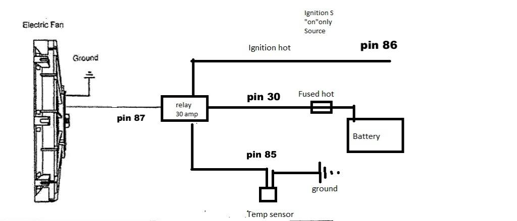
Here is a schematic of how I made my fan setup.
Your car being an 84, I don't believe it had an electric fan. My 84 V6 had a fan clutch. Why exactly do you have a resistor on the fan circuit? That would lower the voltage and increase the load. Looks like something Dodge used in the 70s.
Here is a schematic of how I made my fan setup.

Last edited by Joe Tag; 11-03-2013 at 12:19 PM.
11-03-2013, 09:42 AM
#7
Re: Cooling fan help!!
If you want manual switching,(IDK why you would) just substitute a switch for the temp sensor. Run the same setup for the second fan, or you can have one on a sensor, and the other manually switched.
Trending Topics
11-03-2013, 10:35 AM
#10
Junior Member
Thread Starter
Join Date: Aug 2013
Location: Farmington, Maine
Posts: 57
Likes: 0
Received 0 Likes
on
0 Posts
Car: 1984 Pontiac Firebird S/E
Engine: LG4 305
Transmission: Borg-Warner T5
Axle/Gears: 3.73
Re: Cooling fan help!!
Okay guys thank you. And I don't have a ballast resistor in my fan circuit because about two days after I bought the car I disconnected it because it was stupid. I bought the car the way it was. That resistor is for my HEI coil. The dumbass that sold it to me just happened to think it was a good idea to wire it there because it gave him 12V switched power I assume ahaha. I also just went searching around in my fusebox with a multimeter at the garage today and realized there is more than one place to get 12V power. The two female inputs that say IGN give me 12V switched power and I don't have to run my gauges and radio of the switched accessory circuit thats running my coil and ignition. I think thats why I burned up my starter fuseable link. I was running my 12V switched power to the relay off that wire that was running my ignition/ coil gauges radio ect WAY to much load. Now when I do this again I'll use those IGN inputs to run the relays. I'll also put an inline 5amp fuse to save myself anymore damage ahaha. I also think I was running to high of an amperage on my fuses between the battery and relay last time, 40AMP and a 40 AMP relay. Too high? Oh btw could somebody confirm that it is safe to get the 12v switched power from those IGN inputs? Thanks for the help everyone!
11-03-2013, 10:42 AM
#11
Re: Cooling fan help!!
The ign port on the bottom left of the box is fine to power the relay, but you need a fusible link or inline fuse from the battery for the power to the fan. 5 amps will work for the relay as well, but at least 30 for the fan power. Lose the resistor altogether, and it can't hurt to run a little heavier gage wire in place of the supply line that was going in to it.
11-03-2013, 10:59 AM
#12
Junior Member
Thread Starter
Join Date: Aug 2013
Location: Farmington, Maine
Posts: 57
Likes: 0
Received 0 Likes
on
0 Posts
Car: 1984 Pontiac Firebird S/E
Engine: LG4 305
Transmission: Borg-Warner T5
Axle/Gears: 3.73
Re: Cooling fan help!!
That resistor is there for my ignition coil, it is necessary and in no way once I'm done wiring my fans will have any connection to that circuit. The only reason it did last time was because I tapped into the wire that is powering it and it cause something very bad to happen, enough to melt a fusible link. Now I should be fine now that I found the IGN input and will be fusing that switched 12V power. I have two 20amp lighted switches that have three prongs that say Power, ACC, Ground. JUST TO MAKE SURE! The power prong goes to the 86 prong on the relay, the ACC prong goes to the fuse box 12V fused switched power? Ground is ground obviously. Please confirm I'm right or wrong hahaa.
11-03-2013, 11:18 AM
#13
Re: Cooling fan help!!
Here's a thread that may help you out.
http://www.mp3car.com/the-faq-empori...ire-it-up.html
If you have an HEI dizz that resistor has no place in your car.They run on 12v. It would be a performance downgrade, you are running less than 12v on a 12v ignition system.
http://www.mp3car.com/the-faq-empori...ire-it-up.html
If you have an HEI dizz that resistor has no place in your car.They run on 12v. It would be a performance downgrade, you are running less than 12v on a 12v ignition system.
Last edited by Joe Tag; 11-03-2013 at 11:30 AM.
11-03-2013, 11:33 AM
#14
Junior Member
Thread Starter
Join Date: Aug 2013
Location: Farmington, Maine
Posts: 57
Likes: 0
Received 0 Likes
on
0 Posts
Car: 1984 Pontiac Firebird S/E
Engine: LG4 305
Transmission: Borg-Warner T5
Axle/Gears: 3.73
Re: Cooling fan help!!
So you're saying the ACC prong on the switch goes to the 86 pin on the relay and the power prong on the switch goes to the 12v switched power in the fusebox?
11-03-2013, 11:54 AM
#15
Re: Cooling fan help!!
I edited the diagram in photobucket, but it's not showing here yet.
-30 = constant [positive (+)] power (usually wired directly to car battery)
-85 = coil ground (wired to the negative (-) battery terminal or any grounded metal panel in the car)
-86 = coil power (wired to the control source. could be a switch, or it could be the car's IGN or ACC circuit.)
-87 = switched [positive (+)] power output. (when the relay coil is powered, lead/pin 87 is connected to lead/pin 30)
-87a = [on 5 lead/pin relays only] this lead/pin is connected to lead/pin 30 when the coil is NOT powered.
11-03-2013, 08:32 PM
#17
Supreme Member

iTrader: (13)

Join Date: Apr 2005
Location: Not in Kansas anymore
Posts: 7,733
Likes: 0
Received 11 Likes
on
11 Posts
Car: 82 Z28
Engine: 383 SP EFI/ 4150 TB
Transmission: T400
Axle/Gears: QP 9" 3.73
Re: Cooling fan help!!
My ballast resistor has two wires coming out of it, one going to the starter and one going into my fuse box
When this wire is removed I get no power in the on position but my starter will crank, start the engine for a like a second and the engine will **** down immediately.
When this wire is removed I get no power in the on position but my starter will crank, start the engine for a like a second and the engine will **** down immediately.
Ign switch that keeps it running when the starter stops
Google coil ballast resistor to understand how it works
11-03-2013, 11:18 PM
#18
Supreme Member
Join Date: Apr 2006
Location: Northern, CA
Posts: 4,482
Likes: 0
Received 8 Likes
on
8 Posts
Car: 1989 Iroc-Z Camaro
Engine: TBI,5.0
Transmission: Automatic 700R4
Axle/Gears: Eaton Posi,3.42,LPW Ultimate Cover
Re: Cooling fan help!!
Joe Tag ,
I started using your diagram as my main example when explaining how to wire a fan with an adjustable switch. The thing I like best about it is that when wired in this fashion you don't need to resort to an expensive "high amp" controller. Nice.
I started using your diagram as my main example when explaining how to wire a fan with an adjustable switch. The thing I like best about it is that when wired in this fashion you don't need to resort to an expensive "high amp" controller. Nice.
 11-04-2013, 05:55 AM
#20
Junior Member
Thread Starter
Join Date: Aug 2013
Location: Farmington, Maine
Posts: 57
Likes: 0
Received 0 Likes
on
0 Posts
Car: 1984 Pontiac Firebird S/E
Engine: LG4 305
Transmission: Borg-Warner T5
Axle/Gears: 3.73
Re: Cooling fan help!!
I understand how my coil is powered and works.... I was just explaining all the scenarios. BTW everyone I got the switches working perfectly, no wires get hot or anything. All the important wires have been fused and the system works great. Really helps out when I'm cranking the engine over! If you are also wondering why I wanted a separate switch for each fan, I live in central Maine and often its 60F in the morning and 85 by the end of the day. So rather than having a 175F thermostatic switch I'd much rather have full control myself. Plus the way I mounted the switches they look bad *** ahaha.

Thread
Thread Starter
Forum
Replies
Last Post