1982 Camaro re-wire project
 01-17-2010, 10:10 AM
#1
Supreme Member

Thread Starter
iTrader: (7)
Join Date: Oct 2000
Location: Orange County,NY
Posts: 2,112
Likes: 0
Received 0 Likes
on
0 Posts
Car: 1982 Z28
Engine: 355
Transmission: T56
Axle/Gears: 12 Bolt
1982 Camaro re-wire project
Car is an '82 Camaro that lost all of the computer controls many moons ago. After wiring a few things this summer I really got tired of all the extra wires under the dash. Plus I have added a lot of electrical devices over the years that I didn't do the best job on so I wanted to revisit these areas and make the car dead reliable in terms of its electrical system. Haven't had problems but I needed to make it right ya know.
Anyway enough boring you. I wanted to start this thread to condense all of my questions into one area. Plus with pictures and such it may help get answers when needed. So with all this now said...
This is my main dash harness. I went through it and stripped out what is no longer needed or used. ECM, Choke Heater, Heater wiring. Although this section of wire was pigtailed from GM so I was able to unclip it and remove in case I ever want to reinstall (I liked that). I will be adding a plate under the passenger side of the dash with all of my added relay, MSD box, etc etc. On this plate I needed a switched 12v source and after trimming down the dash harness I was able to relocate the Choke Heater circuit to feed this need. Score! I will have more questions on this "plate" at a later date when I get to making it.
So this is the new slimmed down harness....

Fuse box with only circuits used....

Plugs used to connect to Autometer gauge cluster...

Inline fuse for reverse lockout solenoid on T56. Right now it is wired right to the trans but I plan to add a relay soon. Looking for a timed relay that will turn off after 60 seconds or so. As it sits right now as long as my foot is on the brake pedal and the brake lights are on the RLO is on as well. Don't like the idea of this as I get caught in heavy traffic sometimes in the summer when I use the car for the work commute. Don't want the RLO on that much so a timed relay would be nice. I'll have a 60 second window to stop and be able to put the car in reverse otherwise I just have to let off the brakes and hit them again to reactivate the relay.

Minor details...
Removing the main connector from the firewall proved troublesome. Seems the bolt heads are sunk into the connector body but all the goop on the threads proved to problematic when trying to remove the nuts. The bolt head would just spin inside the connector even though it is locked in on all sides. Took awhile to get these out. So now wanting to go through this again I picked up some allen key headed bolts and nuts in stainless that work very nicely. Small detail but these are the ones I like the best!
Original bolt...

New stainless allen key head...

Now that the harness is done I am revisiting my custom Autometer dash cluster I made years ago. I spliced a few too many wires as I was in a rush t get the car together back then so I want to redo these wires as one solid wire. OCD takes over.
This is a pic of most of the wiring that was removed. Heater wiring on the left side, rear defogger on the right and misc wires in the middle. There are a few plugs and relays that I tossed before I started taking pics. When wires were removed I removed terminals and all from connectors and what not, not just snipped at plugs. 100% removed.

Plenty more pics as I move along!
 04-20-2010, 01:02 PM
#3
Supreme Member
Thread Starter
iTrader: (7)
Join Date: Oct 2000
Location: Orange County,NY
Posts: 2,112
Likes: 0
Received 0 Likes
on
0 Posts
Car: 1982 Z28
Engine: 355
Transmission: T56
Axle/Gears: 12 Bolt
Re: 1982 Camaro re-wire project
Forgot all about this thread. Been so involved trying to get it together for some cruising!
Ok update time!
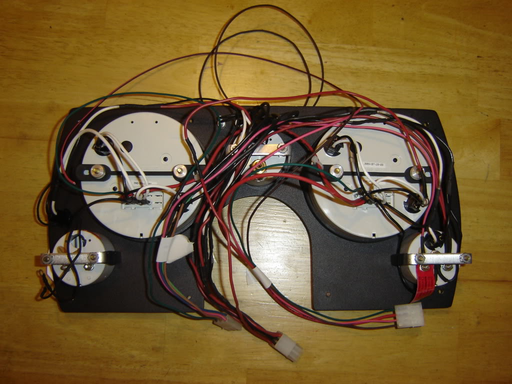
Here is what my gauge cluster looked like with all tie straps removed and getting ready to rewire. Again, no issues as far as functionality but I had some wires that were spliced together. Not happy with that so now is the time to remedy this. I also had to add some wires for the new speedo and tach since I finally installed the matching Sport Comp series. The new speedo is electronic to be able to work with the T56 VSS so I had to change how it was all wired.
This is a template I made for an alternator charge indicator light I am adding. As mentioned in my first post I inadvertently removed a relay for the choke heater that GM used the relay coils resistance to "excite" the alternator. So I have remedied that with an inline resistor as well as an indicator light in the dash to easily verify is the alternator is at least working. And since they run parallel they act as a backup in case one or the other fails.
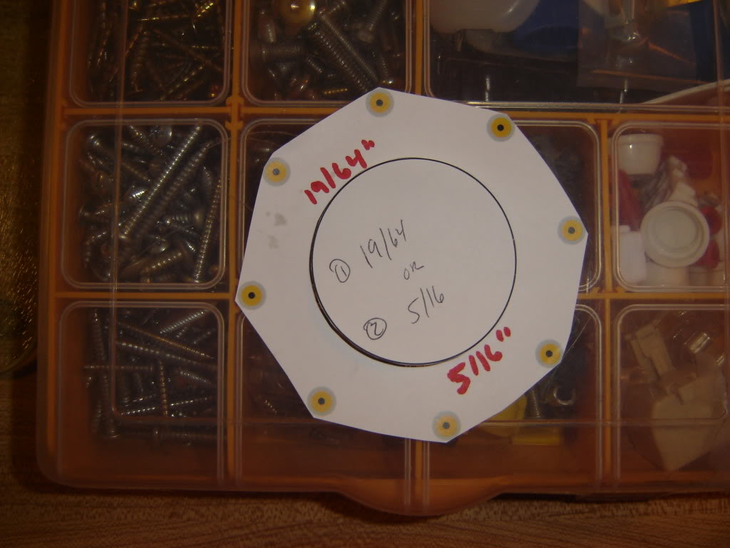
I made the template using the gauge size. Cut the main hole out and slipped it over the gauge and reinstalled the gauge in the cluster. I made the template on the computer placing the indicator light in several spots around the gauge so once in place I could choose which spot I best liked and was easily viewed in car. Worked pretty nice.
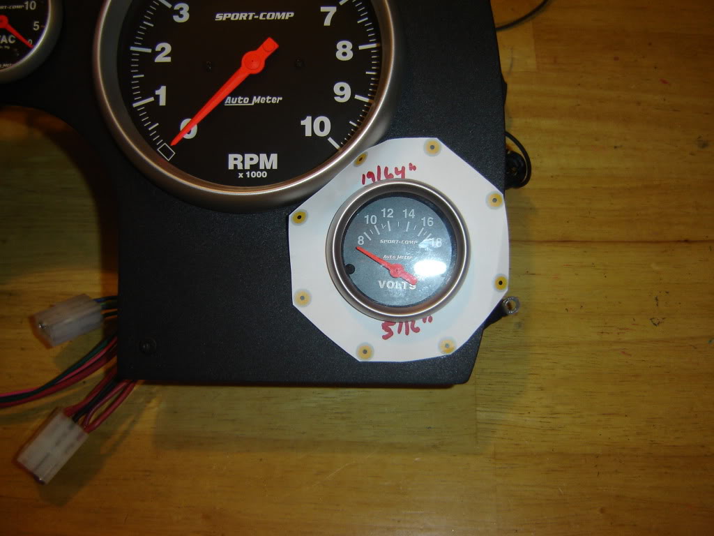
I ended up deciding the spot at the very top and just off to the right filled my needs and desires for the car just right.
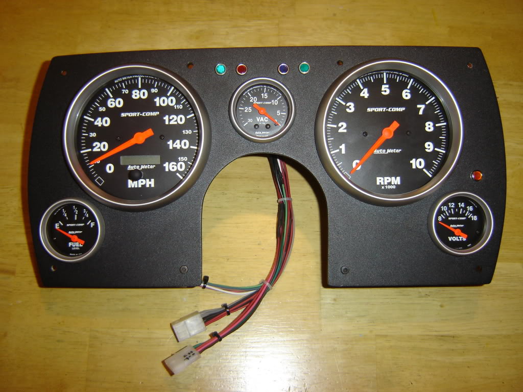
And here is the gauge cluster completed! I am very happy with how it came out. Purpose of this portion of the re-wire was just to clean it up some. All worked great but like I said earlier wires that should be 1 continuous wire were spliced with several sections in my haste in the past. Just wanted it cleaner.Here is a new and improved pic of the back of the gauge cluster. All cleaned up and tied up...
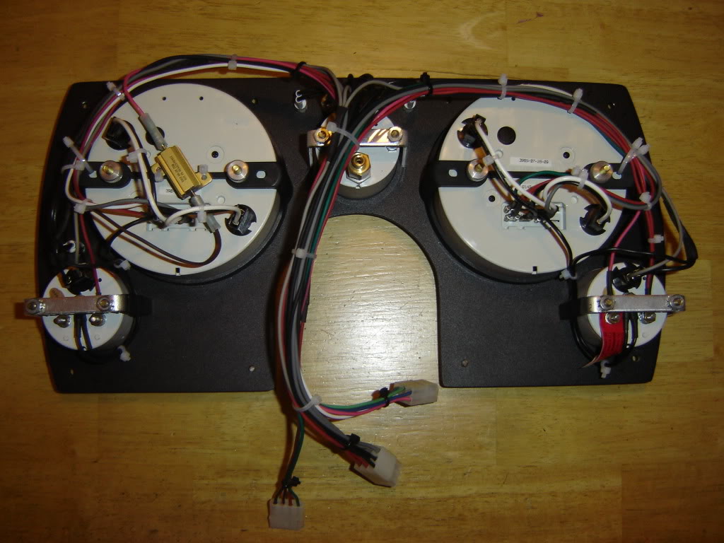
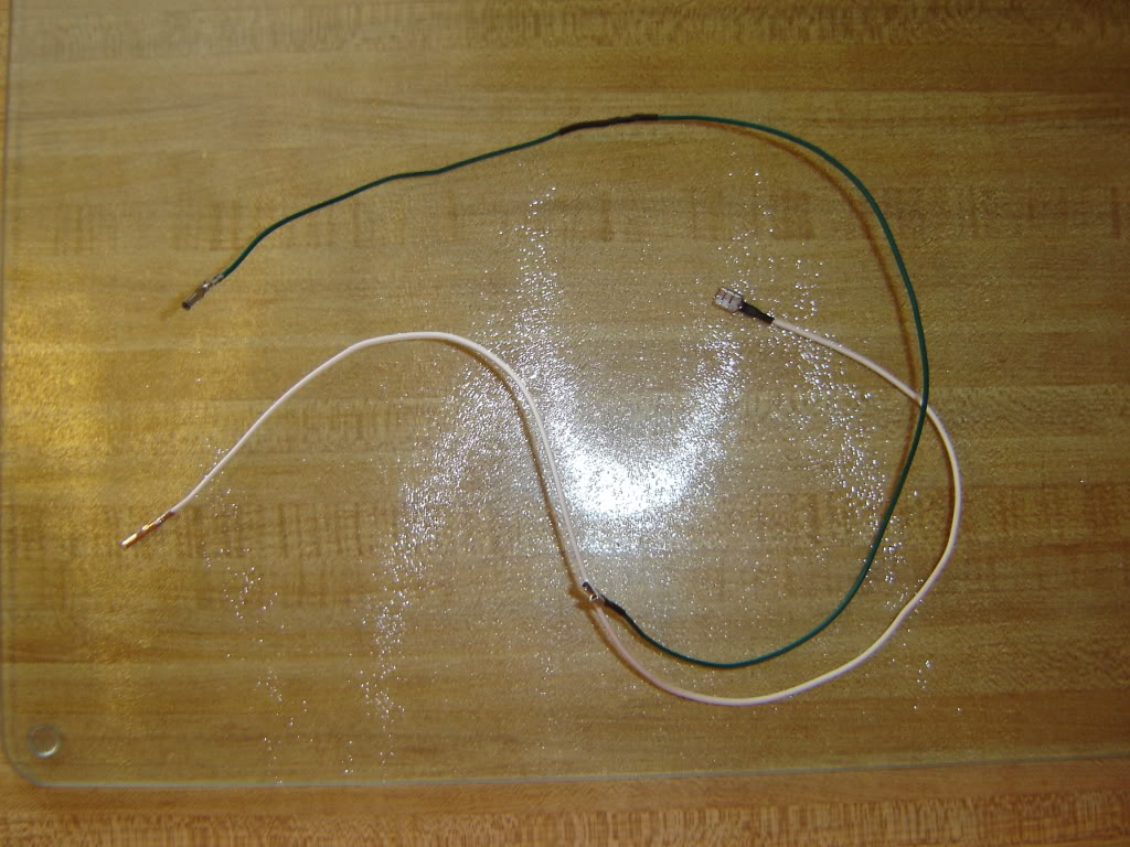
In this pic the green is an old wire that was replaced with a clean piece of white wire.... nothing fancy just a lot neater.
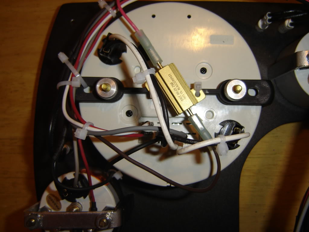
This is the alternator "excite" resistor used in parallel with an indicator light to power the "excite" terminal of the alternator so it can function correctly with my modified harness...
So now I am at... Main dash harness is back in. Gauge cluster is back in. Need to finish up the relay / ignition panel and get that installed. Some small changes for the engine harness and she should start and run (fingers crossed).
This is the start of my relay / ignition panel. This holds my MSD Digital 6, a switched 12v power fuse block to feed assorted circuits. Fans, Line Lock, and Shift Light relays are placed elsewhere in the car so the fuse box just gives them switched power. The other 3 circuits power the relays for the fuel pump relay, clutch relay (activates the 2 step or nitrous progressive controller) all mounted on this board. Took several revisions on the computer to get the layout how I liked it and it seemed to flow the best. Even with all the test fitting and what not it seems to be a lot less room on it now that it is real. But, I have all of the available room used so this is what I have to make work. Plan to make it as easily removed as possible with plugs and such to make it easier to work on if ever needed. Unplug and take it out of the car but when it is in, it completely hides behind the dash!
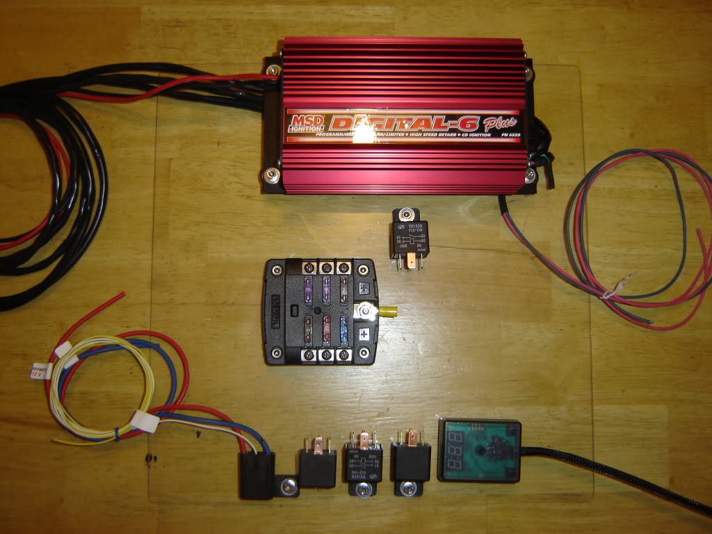
This panel is about 95% wired right now but upon drilling the very last hole for tie strapping wires down a good portion cracked off. Do not use Plexiglas! I have a new piece of ABS plastic that should be in any day. Once in I will transfer the parts over and complete the mounting of that. I will post a new pics of where it stands later today on the broken Plexigas.
At this point all I have to do is finish routing some wires in the engine bay and interior and I will wire in the relay_ignition panel. For now it will lay on the passenger floor just to get the car running and back home where I will have more time to mount the panel and strap all the wires into bundles. I have it in my brother in laws shop and it is an hour round trip just to get there to work on it. I hope to have ignition by sometime next week and bring the car home to complete the interior wiring 100%. More to come....
Ok update time!
Here is what my gauge cluster looked like with all tie straps removed and getting ready to rewire. Again, no issues as far as functionality but I had some wires that were spliced together. Not happy with that so now is the time to remedy this. I also had to add some wires for the new speedo and tach since I finally installed the matching Sport Comp series. The new speedo is electronic to be able to work with the T56 VSS so I had to change how it was all wired.
This is a template I made for an alternator charge indicator light I am adding. As mentioned in my first post I inadvertently removed a relay for the choke heater that GM used the relay coils resistance to "excite" the alternator. So I have remedied that with an inline resistor as well as an indicator light in the dash to easily verify is the alternator is at least working. And since they run parallel they act as a backup in case one or the other fails.
I made the template using the gauge size. Cut the main hole out and slipped it over the gauge and reinstalled the gauge in the cluster. I made the template on the computer placing the indicator light in several spots around the gauge so once in place I could choose which spot I best liked and was easily viewed in car. Worked pretty nice.
I ended up deciding the spot at the very top and just off to the right filled my needs and desires for the car just right.
And here is the gauge cluster completed! I am very happy with how it came out. Purpose of this portion of the re-wire was just to clean it up some. All worked great but like I said earlier wires that should be 1 continuous wire were spliced with several sections in my haste in the past. Just wanted it cleaner.Here is a new and improved pic of the back of the gauge cluster. All cleaned up and tied up...
In this pic the green is an old wire that was replaced with a clean piece of white wire.... nothing fancy just a lot neater.
This is the alternator "excite" resistor used in parallel with an indicator light to power the "excite" terminal of the alternator so it can function correctly with my modified harness...
So now I am at... Main dash harness is back in. Gauge cluster is back in. Need to finish up the relay / ignition panel and get that installed. Some small changes for the engine harness and she should start and run (fingers crossed).
This is the start of my relay / ignition panel. This holds my MSD Digital 6, a switched 12v power fuse block to feed assorted circuits. Fans, Line Lock, and Shift Light relays are placed elsewhere in the car so the fuse box just gives them switched power. The other 3 circuits power the relays for the fuel pump relay, clutch relay (activates the 2 step or nitrous progressive controller) all mounted on this board. Took several revisions on the computer to get the layout how I liked it and it seemed to flow the best. Even with all the test fitting and what not it seems to be a lot less room on it now that it is real. But, I have all of the available room used so this is what I have to make work. Plan to make it as easily removed as possible with plugs and such to make it easier to work on if ever needed. Unplug and take it out of the car but when it is in, it completely hides behind the dash!
This panel is about 95% wired right now but upon drilling the very last hole for tie strapping wires down a good portion cracked off. Do not use Plexiglas! I have a new piece of ABS plastic that should be in any day. Once in I will transfer the parts over and complete the mounting of that. I will post a new pics of where it stands later today on the broken Plexigas.
At this point all I have to do is finish routing some wires in the engine bay and interior and I will wire in the relay_ignition panel. For now it will lay on the passenger floor just to get the car running and back home where I will have more time to mount the panel and strap all the wires into bundles. I have it in my brother in laws shop and it is an hour round trip just to get there to work on it. I hope to have ignition by sometime next week and bring the car home to complete the interior wiring 100%. More to come....
Last edited by onebad82z; 04-20-2010 at 07:23 PM.
 04-20-2010, 08:00 PM
#5
Supreme Member
Thread Starter
iTrader: (7)
Join Date: Oct 2000
Location: Orange County,NY
Posts: 2,112
Likes: 0
Received 0 Likes
on
0 Posts
Car: 1982 Z28
Engine: 355
Transmission: T56
Axle/Gears: 12 Bolt
Re: 1982 Camaro re-wire project
TY.
I am using these polarized plugs from Radioshack whenever I can to make the wiring easy to remove...
http://www.radioshack.com/search/ind...%26+Connectors
All wire is from EFI Connection...
http://www.eficonnection.com/eficonnection/default.aspx
Although I do not think they offer bulk wire any longer. It's a shame as the wire is top quality and very well priced...
04-23-2010, 06:05 AM
#7
Junior Member
Join Date: Aug 2009
Location: Iowa
Posts: 22
Likes: 0
Received 1 Like
on
1 Post
Car: 84 Z28
Engine: 454
Transmission: LT1 T56
Axle/Gears: Moser 12 Bolt Posi with 3.73 gears
Re: 1982 Camaro re-wire project
I agree it looks really good! Can you post a schematic of your new wire loom? How did you wire your RLO into your brake system?
Trending Topics
04-23-2010, 11:18 AM
#8
Supreme Member
Thread Starter
iTrader: (7)
Join Date: Oct 2000
Location: Orange County,NY
Posts: 2,112
Likes: 0
Received 0 Likes
on
0 Posts
Car: 1982 Z28
Engine: 355
Transmission: T56
Axle/Gears: 12 Bolt
Re: 1982 Camaro re-wire project
Thanks guys!
"Can you post a schematic of your new wire loom? How did you wire your RLO into your brake system?"
Schematics are not done yet. I have a ton of notes and some pretty sketchy schematics drawn out as I wired individual systems up. I would draw one up for initial wiring thoughts and as I wired the system I would make notes as I needed to make changes if any at all. Once I know 100% they work as designed and properly I will then commit to designed an actual schematic on the computer. I always do this as I find years later I have to diagnose something and I forgot why I wired it that way.
Now on the RLO all I did for now is take an inline fuse holder and tap into the blue wire that runs from the brake light switch on the pedals and runs to the rear lights. About 5" from the switch I spliced in the inline fuse holder and then connected that wire to the RLO solenoid plug. The other wire off the RLO plug grounds on the framerail. There are 2 wires on the brake light switch for my car, an orange which is constant hot and a light blue that runs to the lights, an output wire. I use a 7.5amp fuse for protection. Now I do plan to change this and add a relay at some point this summer but this inline fuse holder will still be used. I will just swap in a 2amp fuse to protect/activate the relay. Reason for that is right now anytime I have a foot on the brake pedal the RLO is powered. Will it burn out from so much use I cannot say but I want to avoid that if possible. So my plan is to find a timed "on" relay, something like once activated it will only stay on for 60 seconds and then switch back off. That way if I am in traffic like I usually am when using the car for the commute in the summer the RLO is not on the whole time. And when I do need it I want to think from when I hit the brakes to stop and back up if it takes longer than that I can just let up and hit them again to reactivate the relay. Put it in reverse and everyone is happy. This will come as an update later on if I make it happen.
And I have an UPDATE!
I got the car fired up wednesday night. EVERYTHING works as planned aside from one small detail. The car does not shut off with the key. I need to add a diode inline for the alternator excite wiring as the way I modified it allows feedback and the C/H Relay I removed used to perform this function (prevent feedback). Small detail, picking up a diode at lunch today. New ABS panel came in for the relay panel to replace the broken Plexiglass so I am ready there. Plan now is some small odds and ends, change some fluids and bring it home next week. Once home I can swap in the ABS panel and mount it under dash (pics to come) and finish up and wiring left over. She is about 85% done! Forgot how good a solid lifter SB sounds!
08-02-2010, 01:28 PM
#9
Supreme Member
Thread Starter
iTrader: (7)
Join Date: Oct 2000
Location: Orange County,NY
Posts: 2,112
Likes: 0
Received 0 Likes
on
0 Posts
Car: 1982 Z28
Engine: 355
Transmission: T56
Axle/Gears: 12 Bolt
Re: 1982 Camaro re-wire project
Alrighty then. Finally decided to get off my a$$ and finish up this wiring project. Have been having too much fun just cruising the car when I can. Got some tuning out of the way as well as some other bugs and now need to complete this section.
So I finally took the ignition / relay panel out and moved it over to the new ABS plastic panel I bought. Got that done and finished wiring the panel itself with plugs and such to make it easily removed if need be.
Now I just have to complete the mounting of it and the heavy power wires and she is wired.
 04-15-2011, 01:56 PM
#10
Supreme Member
iTrader: (35)
Join Date: Aug 2006
Location: Mississauga,Ont,Canada
Posts: 1,470
Likes: 0
Received 1 Like
on
1 Post
Car: 89 IROC
Engine: LSX 6.0 370, TU2 Cam, Fast intake
Transmission: T56 w/ lots of goodies
Axle/Gears: 8.8, Posi, 4.10, 31 Spline
Re: 1982 Camaro re-wire project
Wow I had to resurect this thead as Im about to do the same autometer set up and had to say that this is clean as hell and I hope to do the same thing soon. Thanks for all the info and pics to help me out
04-15-2011, 02:05 PM
#11
Supreme Member
Thread Starter
iTrader: (7)
Join Date: Oct 2000
Location: Orange County,NY
Posts: 2,112
Likes: 0
Received 0 Likes
on
0 Posts
Car: 1982 Z28
Engine: 355
Transmission: T56
Axle/Gears: 12 Bolt
Re: 1982 Camaro re-wire project
No problem, glad to see it is useful somehow.
Any questions feel free to ask. I am about to start driving it again for this season and plan on starting to re-wire the engine bay wiring. Want to get the headlights wired with relays like in the tech article here on the board. Added fans and some other stuff years ago and although neat I want to set it all up on its own panel like I did for the interior.
Any questions feel free to ask. I am about to start driving it again for this season and plan on starting to re-wire the engine bay wiring. Want to get the headlights wired with relays like in the tech article here on the board. Added fans and some other stuff years ago and although neat I want to set it all up on its own panel like I did for the interior.
04-15-2011, 02:23 PM
#12
Supreme Member
iTrader: (35)
Join Date: Aug 2006
Location: Mississauga,Ont,Canada
Posts: 1,470
Likes: 0
Received 1 Like
on
1 Post
Car: 89 IROC
Engine: LSX 6.0 370, TU2 Cam, Fast intake
Transmission: T56 w/ lots of goodies
Axle/Gears: 8.8, Posi, 4.10, 31 Spline
Re: 1982 Camaro re-wire project
Do you have any pics of it in the car with the column as im making mine at this exact moment and would like to see how the bottom to gauges look when you are driving. I wil have lots of questions for sure. Like did you wire the gauges to the stock harness or did you make your own
Thanks Ray
Thanks Ray
04-15-2011, 02:31 PM
#13
Supreme Member
Thread Starter
iTrader: (7)
Join Date: Oct 2000
Location: Orange County,NY
Posts: 2,112
Likes: 0
Received 0 Likes
on
0 Posts
Car: 1982 Z28
Engine: 355
Transmission: T56
Axle/Gears: 12 Bolt
Re: 1982 Camaro re-wire project
Pics of in installed�
https://www.thirdgen.org/forums/body...er-custom.html
I cut the plugs off of the factory harness and soldered terminals on and added the plugs to adapt the Autometer gauge harness I made. What wires were no longer used were removed in the "re-wire".
https://www.thirdgen.org/forums/body...er-custom.html
I cut the plugs off of the factory harness and soldered terminals on and added the plugs to adapt the Autometer gauge harness I made. What wires were no longer used were removed in the "re-wire".
04-15-2011, 02:37 PM
#14
Supreme Member
iTrader: (35)
Join Date: Aug 2006
Location: Mississauga,Ont,Canada
Posts: 1,470
Likes: 0
Received 1 Like
on
1 Post
Car: 89 IROC
Engine: LSX 6.0 370, TU2 Cam, Fast intake
Transmission: T56 w/ lots of goodies
Axle/Gears: 8.8, Posi, 4.10, 31 Spline
Re: 1982 Camaro re-wire project
Do you know of any wiring diagram I can use to see what gauge wire is what in the harness. I will be doing the same thing in eliminating the CPU / ECU stuff as I have a carb car. Sorry for all the questions
04-15-2011, 02:58 PM
#15
Supreme Member
Thread Starter
iTrader: (7)
Join Date: Oct 2000
Location: Orange County,NY
Posts: 2,112
Likes: 0
Received 0 Likes
on
0 Posts
Car: 1982 Z28
Engine: 355
Transmission: T56
Axle/Gears: 12 Bolt
Re: 1982 Camaro re-wire project
No need to apologize.
I used the wiring diagram in the back of my Haynes manual. Printed it out and taped it all together as a complete diagram. In that diagram they would label a wire as "3.0 BLK" where 3.0 is the wire gauge and BLK is color obviously.
3.0 is the metric size as used by GM. Check out the first table on this page to see how it converts over to standard AWG sizes�
http://www.rbeelectronics.com/wtable.htm
I later on picked up an actual GM service manual for my '82 and it had the exact same diagram in it. If you have a Haynes it should get you started but I would still highly recommend picking up an actual GM service manual for your year. They have a lot of information in it on the wiring, locations of splices, etc.
04-18-2011, 10:08 PM
#16
Junior Member
iTrader: (1)

Join Date: Jun 2010
Location: MI U.P.
Posts: 38
Likes: 0
Received 0 Likes
on
0 Posts
Car: '84 Z28
Axle/Gears: 98 T/A 10 bolt. Auburn, 3.42
Re: 1982 Camaro re-wire project
I was wondering if you could explain your alternator resister exciter circuit in greater detail. My wiring harness is a bit hacked up, so I don't know where to find the choke heater relay wires, if they're even there. From what I understand, a 10 ohm resistor can be used, the warning lamp, the choke heater, or the gauge? and the diode is in there somewhere to prevent feedback?
04-19-2011, 05:01 AM
#17
Supreme Member
iTrader: (35)
Join Date: Aug 2006
Location: Mississauga,Ont,Canada
Posts: 1,470
Likes: 0
Received 1 Like
on
1 Post
Car: 89 IROC
Engine: LSX 6.0 370, TU2 Cam, Fast intake
Transmission: T56 w/ lots of goodies
Axle/Gears: 8.8, Posi, 4.10, 31 Spline
Re: 1982 Camaro re-wire project
With the T56 how did you hook up the speedo for it. I was gonna use the VSS but I dont know if it will work as I dont have a ECM as im going carb. Thanks
04-19-2011, 08:27 AM
#18
Supreme Member
Thread Starter
iTrader: (7)
Join Date: Oct 2000
Location: Orange County,NY
Posts: 2,112
Likes: 0
Received 0 Likes
on
0 Posts
Car: 1982 Z28
Engine: 355
Transmission: T56
Axle/Gears: 12 Bolt
Re: 1982 Camaro re-wire project
I was wondering if you could explain your alternator resister exciter circuit in greater detail. My wiring harness is a bit hacked up, so I don't know where to find the choke heater relay wires, if they're even there. From what I understand, a 10 ohm resistor can be used, the warning lamp, the choke heater, or the gauge? and the diode is in there somewhere to prevent feedback?
This was information supplied to me by a member of this board and got me started.... thanks again sofakingdom!
And with that know I wired my excite circuit as follows:
The brown wire in question from the bulkhead connector ( comes from the alternator plug and into the car through the main firewall plug ) connects to one side of the painless indicator light. From the other side of the light I left the other half of this brown wire as factory wired as it connects to the fuse boxs C/H fuse (20 amp) since it used to run through this circuit anyway. Then I added this resistor in parallel with the light...
http://www.newark.com/vishay-dale/rh...63?Ntt=65k1863
Not sure a generic 10 ohm resistor is going to cut it here. This is all located right behind the dash cluster making it easy to get to if needed. I have had zero issues and alternator charged perfectly since I first wired it this way.
If you are looking to remove the ECM and all related wiring this is probably going to be the easiest way to wire up the excite circuit. I had no use for the original choke heater relay and wanted it gone. Had I know it was actually part of this circuit I may have left it at that time but later thinking about it would have wanted it gone anyway. I like the simplicity of this circuits modified wiring.
CH Relay wiring in my car was light blue in color. Relay was located in the "relay convenience center" which is over your right leg next to the console.
Now the problem I found with this wiring is there is no "kill switch" so to say once the CH relay is removed. What I mean by that is the CH relay is powered up when the car starts, "exciting" the alternator to charge. When the car is shut off the CH relay also turns off killing any chance the alternator can feedback through the excite circuit and keep the car running. With my modified wiring it was able to do so and when I shut the car off it would continue to run. Adding a diode in the wire that runs to the alternator fixed this nicely. I used a 6 amp model from Radio Shack. Soldered a male spade on each end of it. I then soldered female connectors on the wire ( brown of the excite circuit ) about 6" before it runs in the main firewall plug inside the car. I put the diode inline and covered it with a small piece of harness tubing. Works like a charm, is out of the elements and easily changed if needed. I keep a spare or tow in the console just in case.
Diode I used: Radio Shack Rectifier Diode #276-1661
http://www.summitracing.com/parts/ATM-3989/
Ground one side of the factory T56 VSS and connect the other wire to the output terminal of the speedo. Wire the rest of the speedo per Autometer and program it once driving, takes 2 miles and you push the trip button twice. Once when you take off and again at a marked 2 mile spot. Done. Can be programmed to any tire/gear combo. I liked the simplicity of the wiring and it matched my dash I already made so it was a no brainer for me.
Last edited by onebad82z; 04-19-2011 at 08:31 AM.
04-19-2011, 06:00 PM
#19
Junior Member
iTrader: (1)
Join Date: Jun 2010
Location: MI U.P.
Posts: 38
Likes: 0
Received 0 Likes
on
0 Posts
Car: '84 Z28
Axle/Gears: 98 T/A 10 bolt. Auburn, 3.42
Re: 1982 Camaro re-wire project
excellent information, thank you very much! My camaro is charging and choke heater works like a champ
04-21-2011, 11:36 AM
#20
Supreme Member
iTrader: (35)
Join Date: Aug 2006
Location: Mississauga,Ont,Canada
Posts: 1,470
Likes: 0
Received 1 Like
on
1 Post
Car: 89 IROC
Engine: LSX 6.0 370, TU2 Cam, Fast intake
Transmission: T56 w/ lots of goodies
Axle/Gears: 8.8, Posi, 4.10, 31 Spline
Re: 1982 Camaro re-wire project
thanks as well again for answering all my questions

Thread
Thread Starter
Forum
Replies
Last Post